
Modulator fluid
- Make
- Rover
- Model
- 600 Rover 600 Repair Manual - Volumes 1 and 2 - 2nd Edition
- Section
- Repairs › Modulator fluid
Brakes – ABS BY4Modulator fluid
MODULATOR FLUID
CAUTION: Do not spill brake fluid it may damage painted surfaces, wash it off immediately with water.
Do not reuse drained brake fluid.
DO NOT loosen the relief plug on the accumulator.
Release fluid pressure
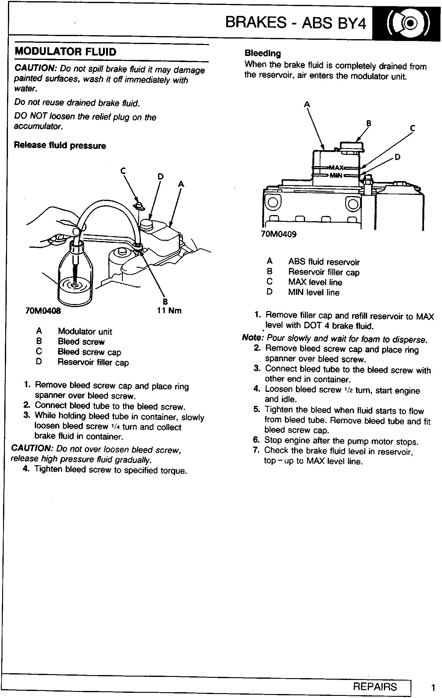
- Modulator unit
- Bleed screw
- Bleed screw cap
- Reservoir filler cap
- Remove bleed screw cap and place ring spanner over bleed screw.
- Connect bleed tube to the bleed screw.
- While holding bleed tube in container, slowly loosen bleed screw ¼ turn and collect brake fluid in container.
CAUTION: Do not over loosen bleed screw, release high pressure fluid gradually.
- Tighten bleed screw to specified torque.
Bleeding
When the brake fluid is completely drained from the reservoir, air enters the modulator unit.
- ABS fluid reservoir
- Reservoir filler cap
- MAX level line
- MIN level line
- Remove filler cap and refill reservoir to MAX level with DOT 4 brake fluid.
Note: Pour slowly and wait for foam to disperse.
- Remove bleed screw cap and place ring spanner over bleed screw.
- Connect bleed tube to the bleed screw with other end in container.
- Loosen bleed screw ½ turn, start engine and idle.
- Tighten the bleed when fluid starts to flow from bleed tube. Remove bleed tube and fit bleed screw cap.
- Stop engine after the pump motor stops.
- Check the brake fluid level in reservoir, top – up to MAX level line.
Parts & tools for this job For Rover 600
- TOOLOBD2 scanner with ABSSearch: OBD2 scanner ABS SRS
- TOOLDigital multimeterSearch: automotive digital multimeter
Links open Amazon search results in a new tab. As an Amazon Associate I earn from qualifying purchases.