
Installation
- Make
- Rover
- Model
- 600 Rover 600 Repair Manual - Volumes 1 and 2 - 2nd Edition
- Section
- Repairs › Installation
Brakes – ABS BY4Installation
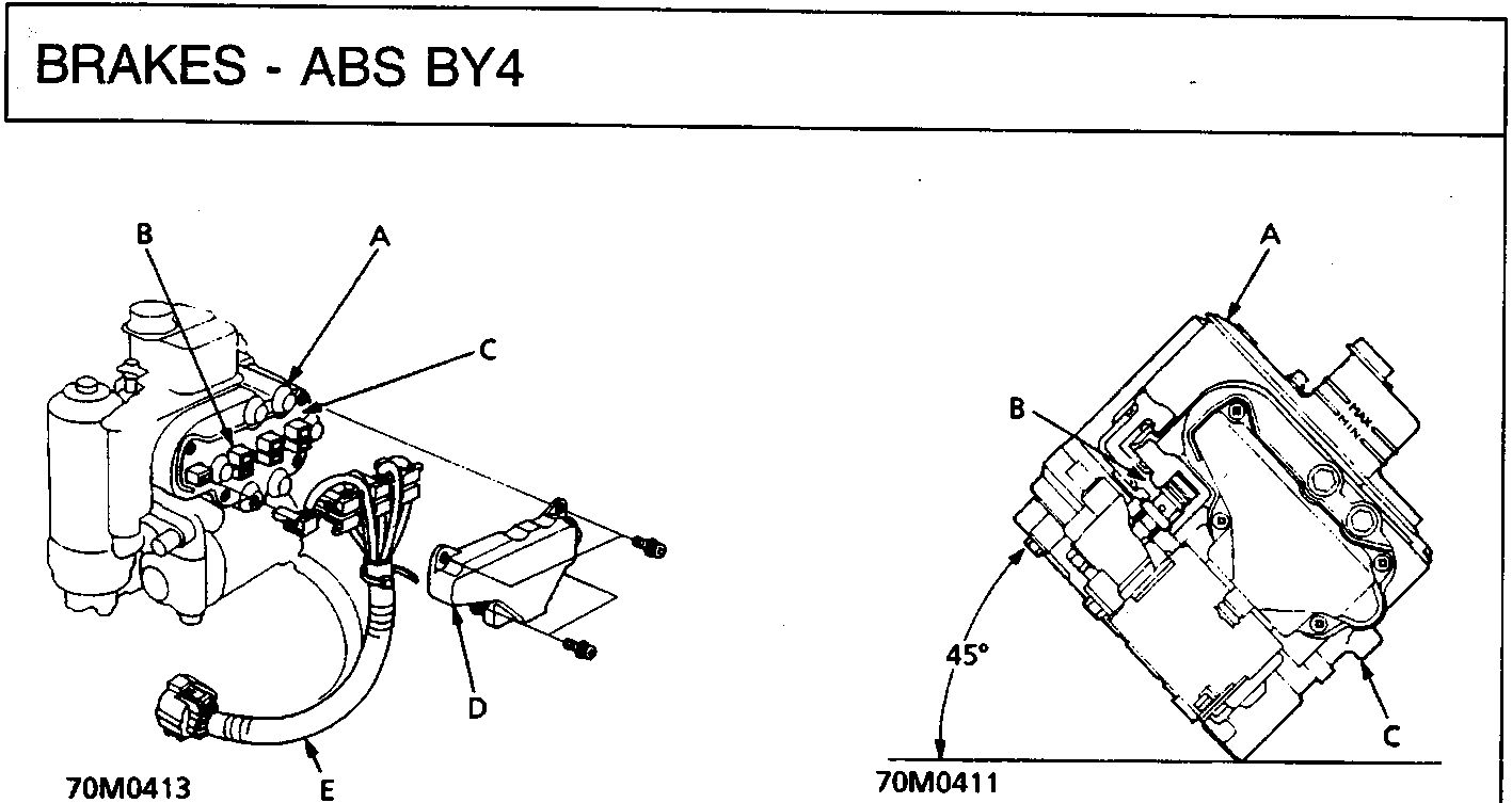
A Modulator unit
B Solenoid connectors
C Set plate
D Cover
E Harness
A ABS reservoir
B Suction port
C Modulator unit
- Release 3 screws and remove the modulator unit cover.
- Note the connector numbers and disconnect the harness.
- Check fluid level in reservoir, top – up the MAX level mark with DOT 4 brake fluid.
- Bleed air from the suction port by leaning modulator unit over to 45° (as shown).
Installation
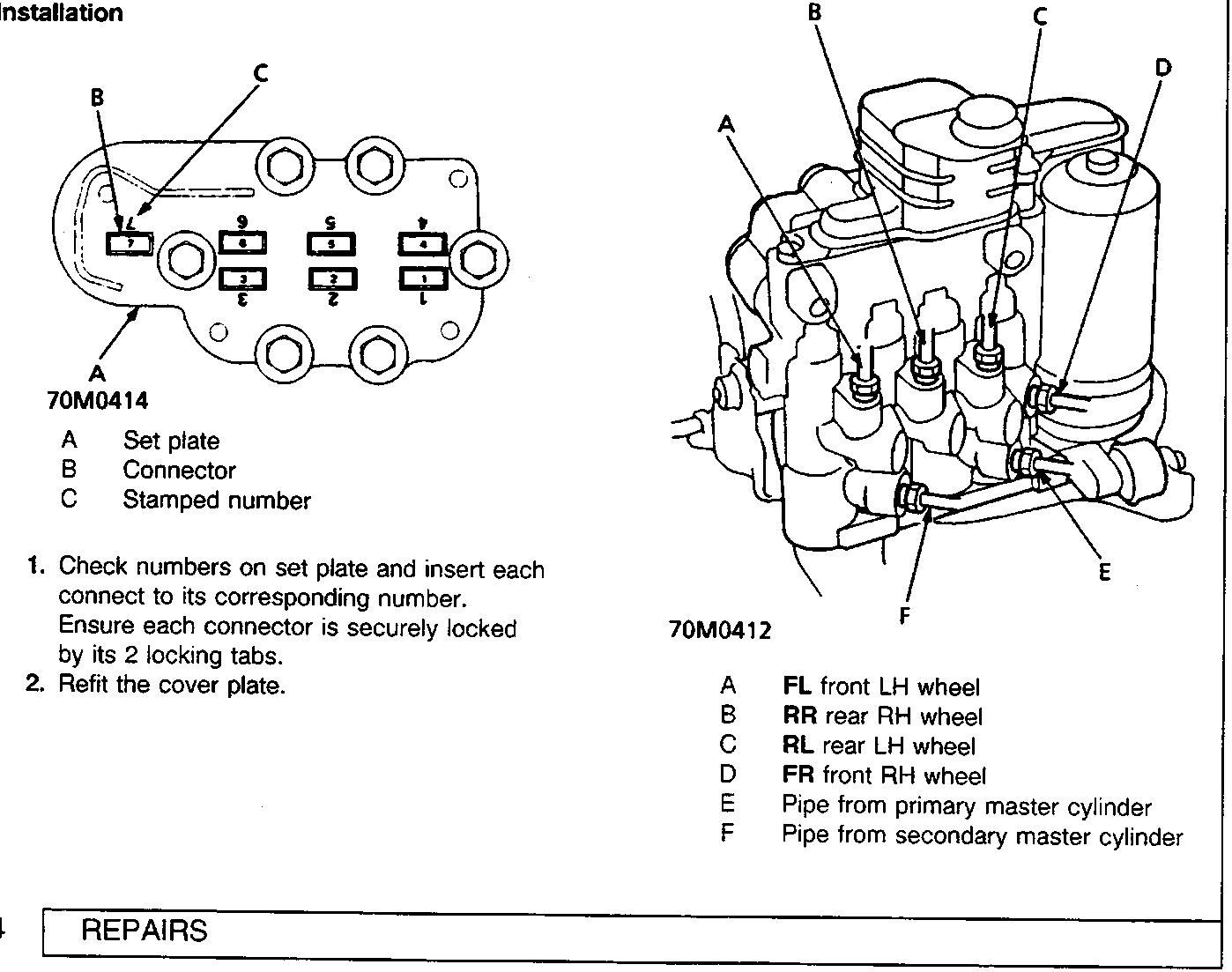
A Set plate
B Connector
C Stamped number
- Check numbers on set plate and insert each connect to its corresponding number. Ensure each connector is securely locked by its 2 locking tabs.
- Refit the cover plate.
A FL front LH wheel
B RR rear RH wheel
C RL rear LH wheel
D FR front RH wheel
E Pipe from primary master cylinder
F Pipe from secondary master cylinder
Parts & tools for this job For Rover 600
- TOOLOBD2 scanner with ABSSearch: OBD2 scanner ABS SRS
- TOOLDigital multimeterSearch: automotive digital multimeter
Links open Amazon search results in a new tab. As an Amazon Associate I earn from qualifying purchases.