
Modulator unit disposal
- Make
- Rover
- Model
- 600 Rover 600 Repair Manual - Volumes 1 and 2 - 2nd Edition
- Section
- Repairs › Modulator unit disposal
Brakes – ABS BY4Modulator unit disposal
MODULATOR UNIT DISPOSAL
WARNING: The accumulator contains high pressure nitrogen gas. Do not puncture, expose to flame, weld or apply impact to the accumulator in an attempt to remove the accumulator from the modulator. The modulator unit may explode and severe injury may result. The accumulator pressure must be discharged before disposal of the modulator unit.
- Remove the modulator assembly,
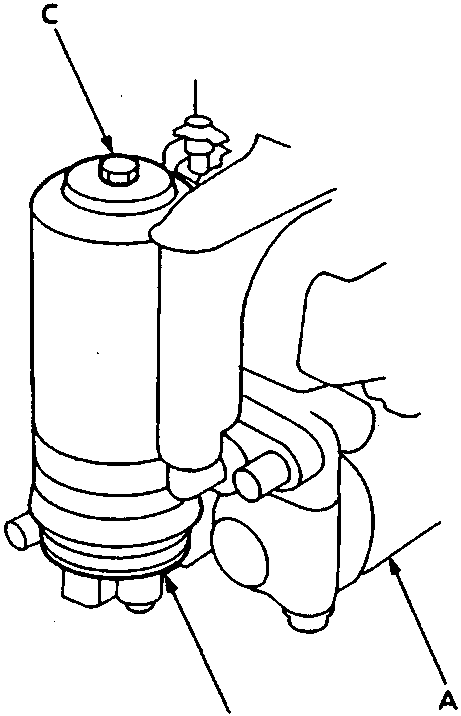
- Modulator unit
- Accumulator
- Relief plug
- Hold modulator in a vice, relief plug uppermost.
- Slowly loosen relief plug 3½ turns and wait 3 minutes for all pressure to escape.
- Remove the relief plug from the accumulator.
- Modulator unit is now safe for disposal.
ABS CONTROL UNIT
Removal/Installation
CAUTION: SRS harnesses are routed near the ABS control unit.
All SRS harnesses are covered with YELLOW Cinsulation.
Before disconnecting any part of the SRS harness, connect short connectors.
Replace the entire affected SRS harness assembly if it has open circuit or damaged wiring.
- Remove the front console assembly, see BODY
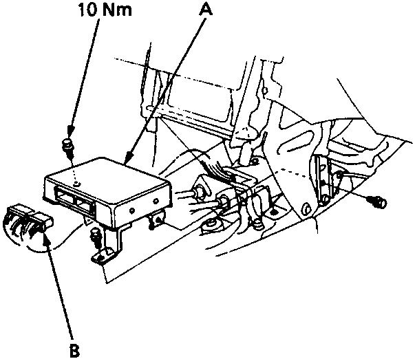
- ABS control unit
- ABS control unit connectors
- Disconnect 2 connectors from the ABS control unit.
- Remove 3 bolts securing the mounting brackets.
- Remove the ABS control unit.
- Install the ABS control unit in the reverse order of removal.
- Install the front console assembly, see BODY
Parts & tools for this job For Rover 600
- TOOLOBD2 scanner with ABSSearch: OBD2 scanner ABS SRS
- TOOLDigital multimeterSearch: automotive digital multimeter
Links open Amazon search results in a new tab. As an Amazon Associate I earn from qualifying purchases.