
Differential Disassembly (page 2 of 2)
- Make
- Rover
- Model
- 600 Rover 600 Repair Manual - Volumes 1 and 2 - 2nd Edition
- Section
- Repairs
Differential – manual gearboxDifferential Disassembly · page 2 of 2
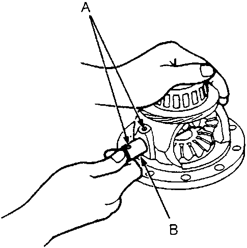
A Align pin holes
B Pinion Shaft
- Rotate gears as shown until shaft holes in pinion gears line up with shaft holes in carrier.
- Insert pinion shaft and align pin hole in one end with matching hole in carrier.
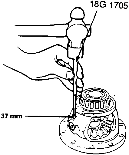
A Pin
- Check the backlash of both pinion gears again.
- Drive the 5 x 37 mm pin using the special tool.
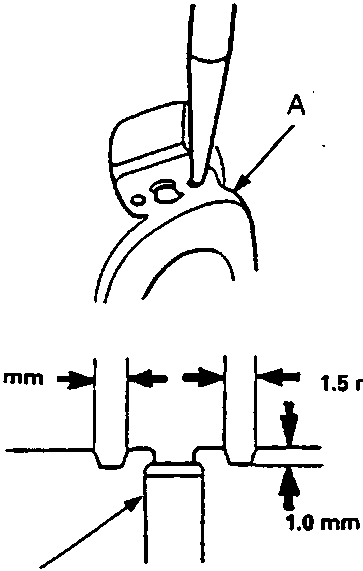
A Differential Carrier
B Pin
- Stake the differential carrier at two points.
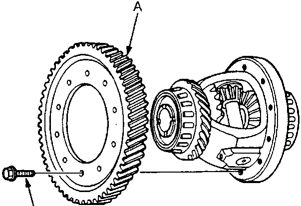
A Chamfer on inside diameter of final driven gear faces carrier.
B Bolt
- Install the final driven gear. Torque the bolts in a crisscross pattern in several steps.
Note: Final driven gear bolts have left-hand threads.
Parts & tools for this job For Rover 600
- PARTClutch kitSearch: Rover 600 clutch kit
- TOOLClutch alignment toolSearch: clutch alignment tool
- FLUIDGear oilSearch: Rover 600 manual gearbox oil
Links open Amazon search results in a new tab. As an Amazon Associate I earn from qualifying purchases.