
Fault finding: Adjustments
- Make
- Rover
- Model
- 600 Rover 600 Repair Manual - Volumes 1 and 2 - 2nd Edition
- Section
- Fault finding › Adjustments
SteeringAdjustments · page 1 of 2
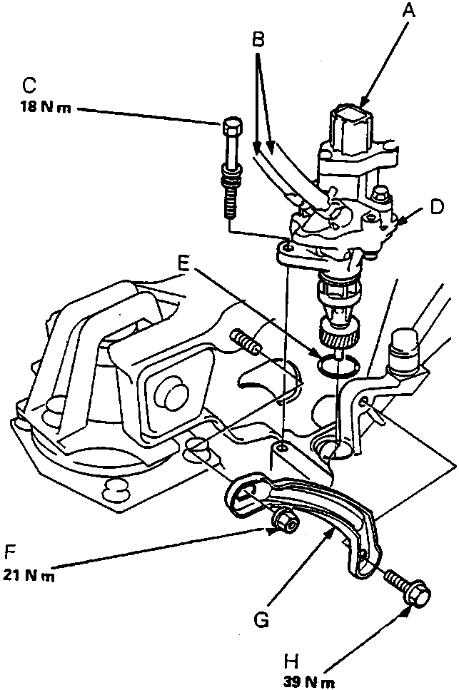
- Remove the rear mount bracket stay nut, then remove the bolt and withdraw the stay.
- Disconnect the vehicle speed sensor (VSS) connector.
- Remove the 8 mm sensor mounting bolt and pull the power steering speed sensor from the transmission housing.
- Disconnect the sensor hoses and plug the fittings.
- After installing a new power steering speed sensor, turn the steering wheel lock-to-lock with the engine idling to bleed air from the system.
- Check the reservoir and add fluid if necessary.
18 N m
21 N m
39 N m
A VSS Connector
B Sensor Hoses
C 8 mm Sensor Mounting Bolt
D Power Steering Speed Sensor
E O-ring
F 10 mm Nut
G Rear Mount Bracket Stay
H 10 mm Bolt
ADJUSTMENTS
Parts & tools for this job For Rover 600
- TOOLTie rod end toolSearch: tie rod end puller
- TOOLBall joint separatorSearch: ball joint separator
- FLUIDPower steering fluidSearch: Rover power steering fluid
Links open Amazon search results in a new tab. As an Amazon Associate I earn from qualifying purchases.