
SRS Unit
- Make
- Rover
- Model
- 600 Rover 600 Repair Manual - Volumes 1 and 2 - 2nd Edition
- Section
- Precautions › SRS Unit
Supplementary restraint system (SRS)SRS Unit
SRS Unit
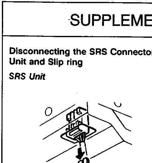
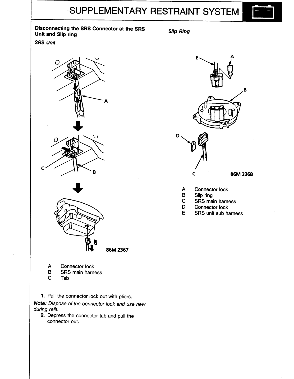
A Connector lock
B SRS main harness
C Tab
- Pull the connector lock out with pliers.
Note: Dispose of the connector lock and use new during refit.
- Depress the connector tab and pull the connector out.
Slip Ring
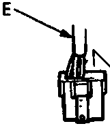
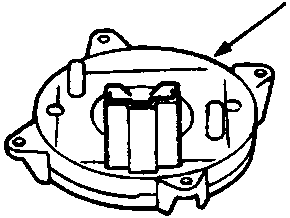
A Connector lock
B Slip ring
C SRS main harness
D Connector lock
E SRS unit sub harness
Original page
Parts & tools for this job For Rover 600
- TOOLOBD2 scanner with SRSSearch: OBD2 scanner ABS SRS
- TOOLTrim removal tool kitSearch: trim removal tool kit
Links open Amazon search results in a new tab. As an Amazon Associate I earn from qualifying purchases.