
General
- Make
- Rover
- Model
- 600 Rover 600 Repair Manual - Volumes 1 and 2 - 2nd Edition
- Section
- Precautions › General
Supplementary restraint system (SRS)General
General
- Carefully inspect any SRS part before you install it. Do not install any part that shows signs of being dropped or improperly handled , such as dents, cracks or deformation:
- Airbag assembly.
- Slip ring.
- Steering wheel.
- Use only a digital circuit tester to check the system. Using an analogue circuit tester may cause an accidental deployment and possible injury.
- Do not install used SRS parts from another car. When repairing an SRS, use only new parts.
- Before beginning work related to the SRS system, turn the ignition switch off, disconnect the negative and positive battery cables, and wait three minutes.
- Replacement of the combination light and wiper/washer switches can be done without removing the steering wheel:
- Combination light and wiper/washer switch replacement.
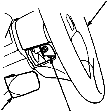
- A Steering wheel
- B LED (in the SRS unit)
- C Access panel
Airbag Handling and Storage
- Do not try to disassemble the airbag assembly. It has no serviceable parts. Once an airbag has been deployed, it cannot be repaired or reused.
- Be careful that the airbag assembly receives no strong shocks; it could deploy.
- Special bolts are necessary for installing the airbag assembly. Do not use other bolts.
For temporary storage of the airbag assembly during service, observe the following precautions:
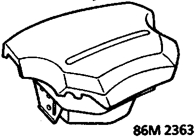
- Store the removed airbag assembly with the pad surface up.
WARNING: If the airbag is improperly stored face down, accidental deployment could propel the unit with enough force to cause serious injury.
- Store the removed airbag assembly on a secure flat surface away from any high heat source (exceeding 85°C/185°F) and free of any oil, grease, detergent or water.
CAUTION: Improper handling or storage can internally damage the airbag assembly, making it inoperative. If you suspect the airbag assembly has been damaged, install a new unit and refer to the Deployment/Disposal Procedures for disposing of the damaged airbag.
- After completed work, check that the connectors are installed tightly:
- The SRS indicator light should go off 6 sec after the ignition switch has been turned on.
- With the ignition switch turned on, the LED of the SRS unit should blink one time.
Parts & tools for this job For Rover 600
- TOOLOBD2 scanner with SRSSearch: OBD2 scanner ABS SRS
- TOOLTrim removal tool kitSearch: trim removal tool kit
Links open Amazon search results in a new tab. As an Amazon Associate I earn from qualifying purchases.