
Damper
- Make
- Rover
- Model
- Coupé, Cabriolet & Tourer 200/400 Coupé, Cabriolet & Tourer Workshop Manual
- Section
- Repairs › Damper
Drive shaftsDamper
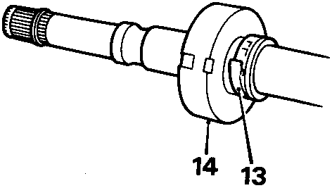
8RM 0801
Damper
- Release damper securing clip and discard it.
- Slide damper from shaft.
- Clean joint and shaft end.
Refit
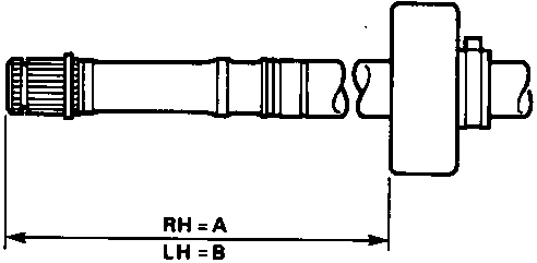
8RM 0802
- Measure along shaft for fitting of damper.
1.4 Models:
R.H. shaft 'A' = 405 – 411 mm
L.H. shaft 'B' = 148 – 154 mm
2.0 Models:
R.H. shaft 'A' = 129 – 135 mm
L.H. shaft 'B' = 139 – 145 mm
Diesel Models:
R.H. shaft 'A' = 165 – 171 mm
L.H. shaft 'B' = No damper - Mark the shaft for fitting position.
- Lubricate shaft to aid fitting of damper.
- Position new clip on shaft.
- Fit damper to shaft with flange facing inner joint.
Note: Dampers for L.H. and R.H. shafts are not interchangeable.
- Fit clip around damper flange.
- Secure damper with clip.
- Clean lubricant from shaft.
- Fit new circlip to shaft.
- Fit gaiter to shaft.
- Position outer joint to shaft, use a screwdriver to press circlip into its groove and push joint fully onto shaft.
- Smear grease from the sachet around joint.
- Position gaiter to joint and use a Band – it thriftool to secure the 2 new clips.
- Fit drive shaft.
- Fit road wheel and tighten nuts to 100 Nm.
- Remove stand(s) and lower vehicle.
OUTER JOINT, GAITER AND DAMPER – 1.6
Service Repair No. Outer joint – 47.10.04
Service Repair No. Gaiter – 47.10.03
Service Repair No. Damper – 47.10.33
Remove
- Raise front of vehicle, one side.
WARNING: Support on safety stands.
- Remove road wheel(s).
- Remove drive shaft.
- Place drive shaft in a vice.
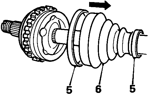
8RM 0798
- Release both gaiter clips and discard.
- Slide gaiter along shaft to gain access to outer joint.
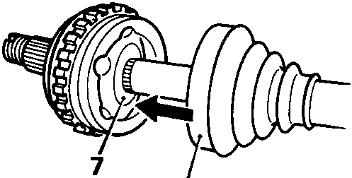
8RM 0799
- Bend the joint and, using a suitable drift against the inner part of joint, remove joint from shaft.
- Slide gaiter from shaft.
- Inspect gaiter for signs of damage and renew if necessary.
Parts & tools for this job For Rover Coupé, Cabriolet & Tourer
- PARTWheel bearingSearch: Rover Coupé, Cabriolet & Tourer wheel bearing
- TOOLBearing puller kitSearch: wheel bearing puller kit
- PARTCV boot kitSearch: Rover Coupé, Cabriolet & Tourer cv boot kit
Links open Amazon search results in a new tab. As an Amazon Associate I earn from qualifying purchases.