
Refit
- Make
- Rover
- Model
- Coupé, Cabriolet & Tourer 200/400 Coupé, Cabriolet & Tourer Workshop Manual
- Section
- Repairs › Refit
Drive shaftsRefit · page 1 of 2
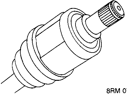
- Remove circlip from drive shaft and discard.
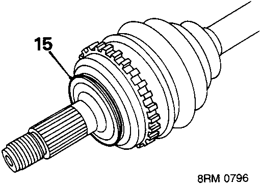
- Inspect seal adjacent to outer joint and renew if worn or damaged.
Refit
- Wipe drive shaft ends, hub and differential oil seal. Lubricate oil seal running surfaces.
- Fit new circlip to drive shaft.
- Engage shaft in differential and push fully home.
CAUTION: Pull joint to ensure circlip is fully engaged and retains shaft.
- Pull hub outwards and connect drive shaft to hub.
- Engage lower ball joint with hub.
- Fit lower ball joint nut and tighten to 60 Nm.
- Secure nut with a new split pin.
- Fit steering arm ball joint to hub.
- Fit steering arm ball joint nut and tighten to 44 Nm.
- Secure nut with a new split pin.
- Fit new drive shaft nut and tighten to 185 Nm. Stake nut to shaft.
- Fit road wheel and tighten nuts to 100 Nm.
- Remove stand(s) and lower vehicle.
- Check and top up gearbox oil, see MAINTENANCE.
DRIVE SHAFT – 1.6
Service Repair No. 47.10.01
Remove
- Raise front of vehicle, one side.
WARNING: Support on safety stands.
- Remove road wheel(s).
- R.H. shaft only: Position drain tin to collect oil spillage from gearbox.
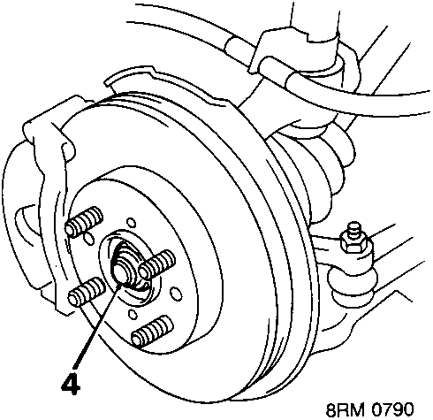
- Knock back staking on drive shaft nut. With an assistant depressing brake pedal, remove drive shaft nut. Discard drive shaft nut.
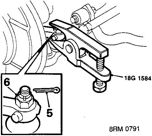
- Remove split pin from steering arm nut.
- Remove steering arm joint nut.
- Break taper joint using 18G 1584.
Parts & tools for this job For Rover Coupé, Cabriolet & Tourer
- PARTWheel bearingSearch: Rover Coupé, Cabriolet & Tourer wheel bearing
- TOOLBearing puller kitSearch: wheel bearing puller kit
- PARTCV boot kitSearch: Rover Coupé, Cabriolet & Tourer cv boot kit
Links open Amazon search results in a new tab. As an Amazon Associate I earn from qualifying purchases.