
Intermediate shaft and support bearing – 1.6
- Make
- Rover
- Model
- Coupé, Cabriolet & Tourer 200/400 Coupé, Cabriolet & Tourer Workshop Manual
- Section
- Repairs › Intermediate shaft and support bearing – 1.6
Drive shaftsIntermediate shaft and support bearing – 1.6
- Fit stopper ring to shaft.
- Fit spider to shaft and secure with circlip.
- Fit bearings to spider with shoulders facing outwards.
- Smear grease from the sachet inside joint and fit joint to shaft.
- Position gaiter to joint and use a Band – it thriftool to secure 2 new clips.
- Fit drive shaft.
- Fit road wheel and tighten nuts to 100 Nm.
- Remove stand(s) and lower vehicle.
INTERMEDIATE SHAFT AND SUPPORT BEARING – 1.6
Service Repair No. Intermediate shaft – 47.10.34
Service Repair No. Support bearing – 47.10.35
Remove
- Raise L.H. front of vehicle.
WARNING: Support on safety stands.
- Remove road wheel(s).
- Remove L.H. drive shaft.
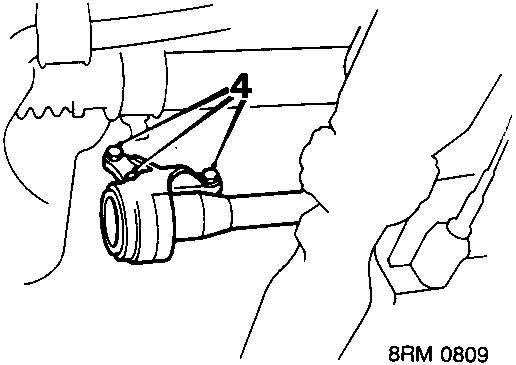
- Remove 3 bolts intermediate shaft bearing housing to cylinder block.
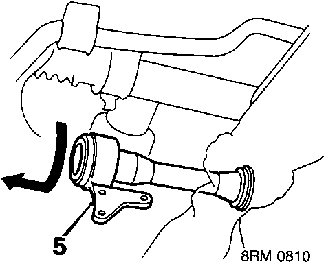
- Rotate shaft so that bearing housing flange faces downwards and release shaft from gearbox.
- Remove intermediate shaft.
CAUTION: Pull the shaft horizontally to avoid damaging the differential oil seal.
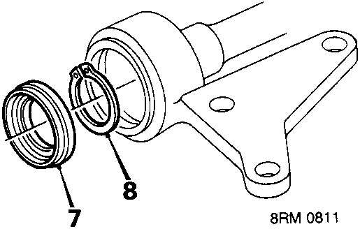
- Prise outer seal from bearing housing.
- Remove circlip from end of shaft.
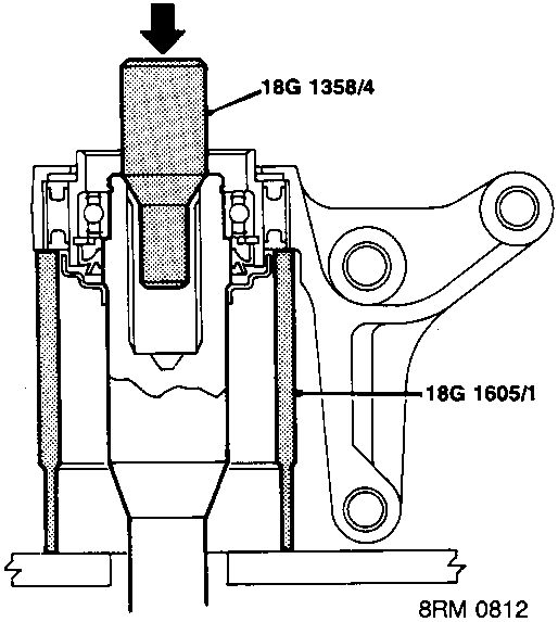
- Support bearing housing on tool 18G 1605/1 and press shaft from bearing housing, using tool 18G 1358/4.
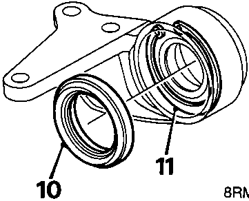
- Remove inner seal from bearing housing.
- Remove circlip retaining bearing.
Parts & tools for this job For Rover Coupé, Cabriolet & Tourer
- PARTWheel bearingSearch: Rover Coupé, Cabriolet & Tourer wheel bearing
- TOOLBearing puller kitSearch: wheel bearing puller kit
- PARTCV boot kitSearch: Rover Coupé, Cabriolet & Tourer cv boot kit
Links open Amazon search results in a new tab. As an Amazon Associate I earn from qualifying purchases.