Power transmissionInput shaft: Dismantling and assembling
| Input shaft: dismantling and assembling |
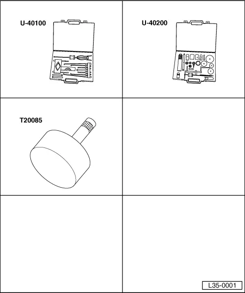
| Special tools and workshop equipment required |
| t
| Gearbox extractor set -U-40100- |
| t
| Gearbox repair set -U-40200- |
| t
| Tool for removing/fitting stop ring 5th gear -T20085- |

Note!
| Whenever new gears are fitted consult the technical data → Chapter, Code letters, group numbers, ratios, filling quantities. |
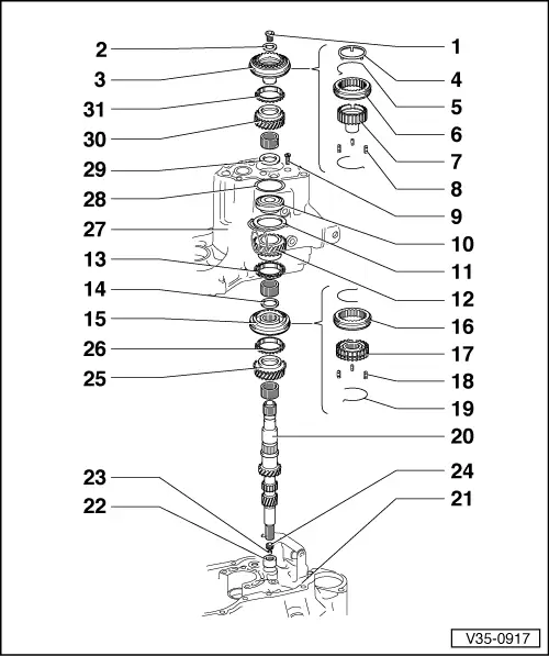
|
q
| Removing and fitting → Chapter, Assembly sequence |
| 3 - | Syncromesh assembly 5th gear |
|
q
| Removing and fitting → Chapter, Assembly sequence |
|
q
| Stops the locking keys from being released |
| 6 - | Sliding sleeve for 5th gear |
|
q
| Installation position → Fig. |
| 7 - | Syncromesh hub 5th gear |
|
q
| Secures the ball bearing |
| 13 - | Syncromesh ring for 4th gear |
| 15 - | 3rd and 4th syncromesh assembly |
|
q
| Remove together with sliding 3rd gear → Fig. |
|
q
| Syncromesh installation position → Fig. |
| 22 - | Needle roller bearing |
|
q
| Removing and fitting → Chapter, Clutch housing: repairing |
| 23 - | Oilseal for clutch pushrod |
|
q
| Can be replaced with the geabox removed (not dismantled) |
|
q
| Remove by levering with a screwdriver → Fig. |
|
q
| Installation position → Fig. |
| 24 - | Bush for clutch pushrod |
|
q
| Can be replaced with the geabox removed (not dismantled) |
|
q
| Installation position → Fig. |
| 26 - | Syncromesh ring 3rd gear |
|
q
| Installation position → Fig. |
|
q
| Once the 5th gear syncromesh ring has been fitted, → Item, fit the sliding 5th gear, → Item, on the syncromesh hub → Item |
| 31 - | Syncromesh ring 5th gear |
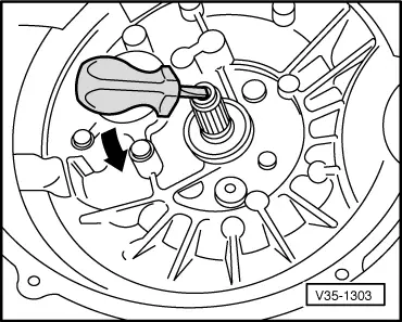
| Remove by levering the clutch pushrod oilseal |
|
|
|
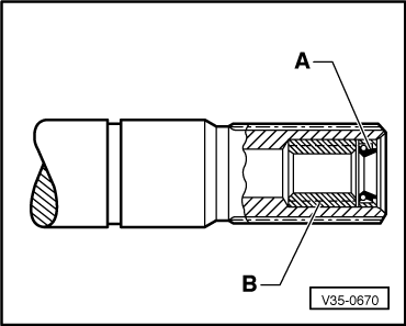
| Assembly position of oilseal and bush |
| A - Oilseal for clutch pushrod |
| B - Bush for clutch pushrod |
|
|
|
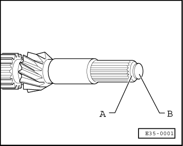
| Fit the clutch pushrod oilseal |
| –
| Fitting the oilseal -A- together with the cap -B- supplied, so that it is flush. Remove assembly cap -B-: the depth of oilseal fitting is now 0.8 … 1.3 mm. Lubricate the oilseal lip lightly. |
|
|
|
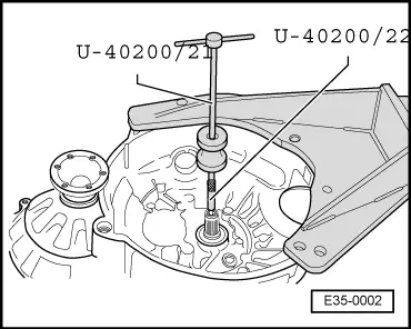
| Remove by levering the clutch pushrod oilseal |
| –
| Screw tool -U-40200/22- into the bush and action the hammer extractor -U-40200/21- to remove the bush. |
|
|
|
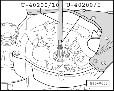
| Fit the clutch pushrod bush home |
|
|
|
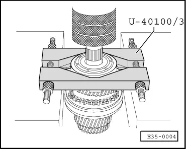
| Removing the roller bearing |
| –
| After separate the tensioning plate, the sliding 4th gear and the needle roller bearing. |
| –
| Remove the syncromesh ring and the circlip that secures the syncromesh hub for 3rd and 4th gear. |
|
|
|
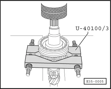
| Remove the 3rd and 4th gear syncromesh assembly with the 3rd gear |
|
|
|
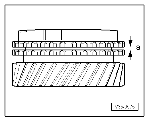
| Checking syncromesh ring wear |
| –
| Press the syncromesh ring onto the cone of the sliding gear and measure dimension -a- with a feeler gauge. |
|
|
|
Syncromesh
ring | Measurement -a-
on a new
syncromesh | Wear limit |
3rd gear
4th gear
5th gear | 1.15 … 1.75 mm
1.3 … 1.9 mm
1.3 … 1.9 mm | 0.5 mm |
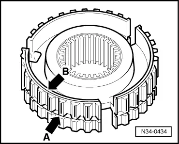
| Assembly position for syncromesh hub, 3rd and 4th gears |
| The shorter teeth under the groove -arrow A- face the 3rd gear. |
| The front groove -arrow B- faces the 4th gear. |
|
|
|
| Assembly of sliding sleeve for 3rd and 4th gear syncromesh hub |
| –
| Slide the sleeve onto the syncromesh hub. |
| The recesses for the syncromesh locking keys and the sleeve mustline up. |
| –
| Insert the locking keys and fit the springs at 120° from each other. The angled ends of the springs must locate in the inner hollow of the corresponding locking keys. |
|
|
|
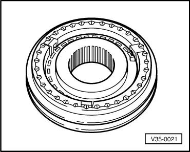
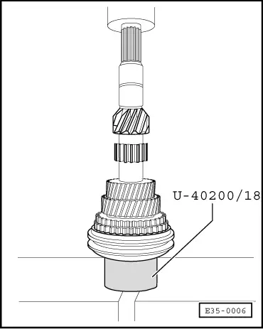
| Fitting the syncromesh assembly for 3rd and 4th gears |
|
|
|
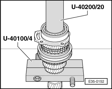
| Assembling the roller bearing |
|
|
|
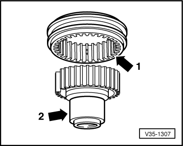
| Assembly position for 5th gear sliding sleeve |
| –
| Slide the sleeve onto the syncromesh hub. |
| The recesses for the syncromesh locking keys and the sleeve mustline up. |
| The bevel on the teeth -arrow 1- faces the 5th gear syncromesh hub shaft -arrow 2-. |
| –
| Insert the locking keys and fit the springs at 120° from each other. The angled ends of the springs must locate in the inner hollow of the corresponding locking keys. |
|
|
|
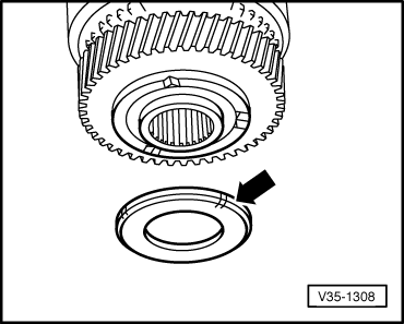
| Assembly position of the sliding 5th gear thrust washer |
| The bevel -arrow- should be opposite the sliding gear. |
|
|
|
| –
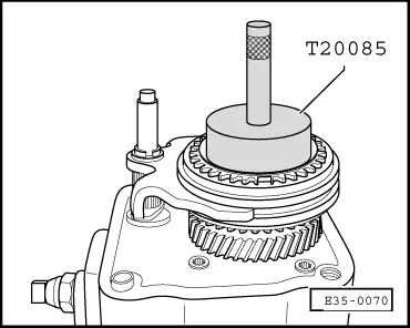
| Place tool -T20085- inside the syncromesh ring/stop assembly and remove the stop circlip. |
|
|
|
| –
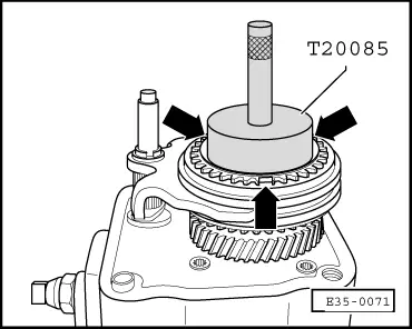
| Insert tool -T20085- inside the stop circlip and locate the clip inside the syncromesh ring. |
| –
| The stop ring tabs should be anchored in the recesses of the syncromesh ring locking keys -arrows-. |
|
|
|
01 Transmission
The same page in:
Leon Mk1.