EngineCylinder Head Replacement
Cylinder Head Replacement
Special tools
| • |
EN-470-B
Torque Angle Sensor Kit |
For equivalent regional tools, refer to
Special Tools .
Removal Procedure

| 6. |
Remove the 2 exhaust pressure
pipe clamps (2, 6). |
| 7. |
Remove the exhaust pressure
pipe bolt (5) from the throttle body support. |
| 8. |
Remove the exhaust pressure
pipe bolt (3) from the exhaust pressure sensor bracket (1).
|
| 9. |
Unclip the vacuum hose from
exhaust pressure pipe (4). |
| 10. |
Remove the exhaust pressure
pipe (4). |
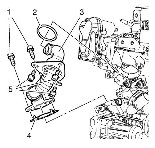
| 11. |
Remove the 2 exhaust gas
recirculation pipe bolts (1) from the exhaust gas recirculation
valve cooler. |
| 12. |
Remove the 3 exhaust gas
recirculation pipe bolts (5) from the exhaust manifold.
|
| 13. |
Remove the exhaust gas
recirculation pipe (3). |
| 14. |
Remove the exhaust gas
recirculation pipe seal (2). |
| 15. |
Remove the exhaust gas
recirculation pipe gasket (4). |
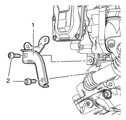
| 16. |
Remove the 2 throttle body
support bolts (2). |
| 17. |
Remove the throttle body
support (1). |
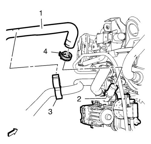
| 18. |
Unclip the heater inlet hose
(1) from the heater outlet hose (3). |
| 19. |
Remove the heater outlet hose
clamp (4). |
| 20. |
Remove the heater inlet hose
(1) from the exhaust gas recirculation valve cooler (2).
|
| 21. |
Disconnect the exhaust gas
recirculation valve wiring harness plug. |
| 22. |
Disconnect the exhaust gas
recirculation valve actuator wiring harness plug. |
| 23. |
Remove the exhaust gas
recirculation valve actuator vacuum hose. |
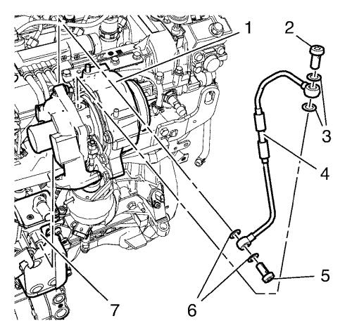
| 24. |
Remove the turbocharger oil
feed pipe bolt (2) from the turbocharger (1). |
| 25. |
Remove the 2 turbocharger oil
feed pipe gaskets (3). |
| 26. |
Remove the turbocharger oil
feed pipe bolt (5) from the oil filter housing (7). |
| 27. |
Remove the 2 turbocharger oil
feed pipe gasket (6). |
| 28. |
Remove the turbocharger oil
feed pipe (4). |
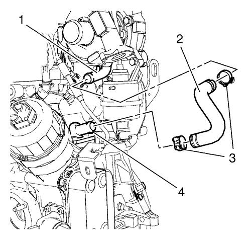
| 29. |
Remove the 2 turbocharger oil
return hose clamps (3). |
| 30. |
Remove the turbocharger oil
return hose (2) from the turbocharger (1) and the oil filter
housing (4). |
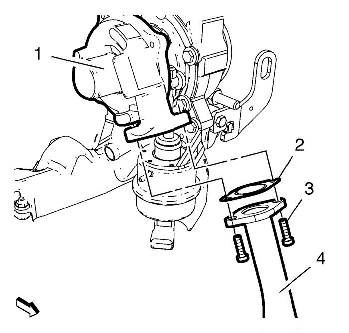
| 31. |
Remove the 2 charge air cooler
inlet air pipe bolts (3). |
| 32. |
Remove the charge air cooler
inlet air pipe (4) from the turbocharger (1). |
| 33. |
Remove the charge air cooler
inlet air pipe gasket (2). |

|
Note: Place clean
rags (2) in the opening to prevent the bolt from falling into the
timing case.
|
| 34. |
Remove the upper timing chain
guide bolt (1). |
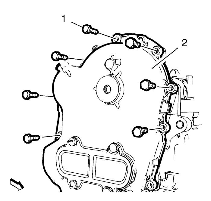
| 35. |
Remove the 3 oil pump housing
bolts (1) from the oil pump housing and the cylinder head.
|
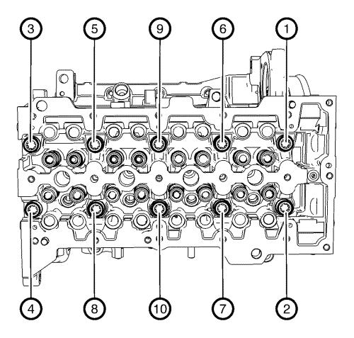
| 36. |
Loosen the 10 cylinder head
bolts in sequence as shown. |
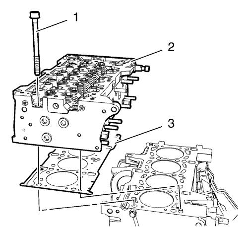
| 37. |
Remove and DISCARD the 10
cylinder head bolts (1). |
| 38. |
Remove the cylinder head
(2). |
| |
38.1 |
Carefully slide the cylinder
head from the oil pump housing and remove it. |
| |
38.2 |
Carefully lever the cylinder
head off the timing case gasket with plastic wedge and use a rubber
mallet to knock it off the timing case. Place the cylinder head on
wooden blocks with the help of a second person. |
| 39. |
Remove the cylinder head
gasket (3). |
| 40. |
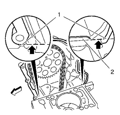
Secure the timing chain with a
cable tie. |
|
Note: Do NOT damage
the sealing lip (2). Make sure that no residues remain at the joint
between the oil pump housing and cylinder block, and that no bits
of the gasket fall into the timing case.
|
| 41. |
Remove the oil pump housing
gasket carefully. |
| |
41.1 |
Cut into the elastomer sealing
lips (arrows) using a sharp knife pressed against the cylinder
head. |
| |
41.2 |
With a plastic spatula, loosen
the gasket from the oil pump housing and carefully snap it off at
the designated point (1). |
| |
41.3 |
Remove the oil pump housing
gasket. |
| |
41.4 |
Remove any gasket residue and
clean all sealing surfaces. |
Installation Procedure
|
Note: Ensure that the
cylinder head and the cylinder block sealing surfaces are clear of
oil, grease and old gasket material.
|
| 8. |
Clean the sealing
surfaces. |
| 9. |
Inspect the flatness of the
cylinder head and the cylinder block sealing surfaces. |

|
Note: A second
technician is required.
|
| 10. |
Set piston of cylinder 1 to
TDC |
|
Note: The timing chain must
be tightened to prevent the chain from slipping when the crankshaft
is turned.
|
| |
10.1 |
Using a suitable tool (2),
press the camshaft drive gear (1) up and fix. |
| |
10.2 |
Turn the crankshaft in the
direction of engine rotation at the crankshaft balancer.
|
|
Note: Carefully lay the
camshaft drive gear on the web on the timing case.
|
| |
10.3 |
Release the timing
chain. |

| 11. |
Install the EN-301
bridge (2) along with the GE-571-B gauge
(1). |
|
Note: The largest
piston projection is decisive for the selection of the cylinder
head gasket with the corresponding marking.
|
| 12. |
Measure the piston projection
dimensions at all pistons. |
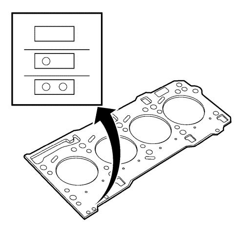
| 13. |
Select the cylinder head
gasket with the correct identification marks: |
| |
13.1 |
Piston projection
0.028 - 0.127 mm (0.001 - 0.005 in) , choose
cylinder head gasket with identification mark - without
holes. |
| |
13.2 |
Piston projection
0.128 - 0.227 mm (0.005 - 0.009 in) , choose
cylinder head gasket with identification mark - one hole.
|
| |
13.3 |
Piston projection
0.228 - 0.327 mm (0.009 - 0.013 in) , choose
cylinder head gasket with identification mark - two holes.
|

| 14. |
Fit the NEW oil pump housing
gasket. |
| |
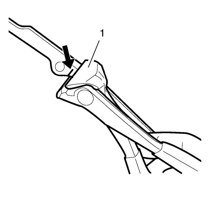
14.1 |
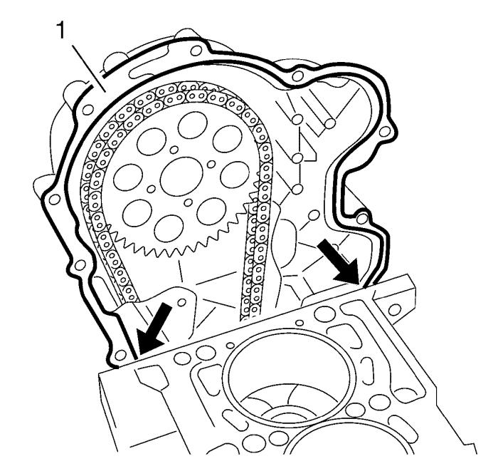
Using a sharp knife, cut into
the elastomer sealing lips (arrows) at the breaking points of the
new gasket. |
|
Note: It is essential for
the cutting tool (1) to have a straight cutting surface.
|
| |
14.2 |
Cut the NEW oil pump housing
gasket off at the breaking points (arrow). |
|
Note: The upper new
gasket and the old lower gasket must not be allowed to overlap.
|
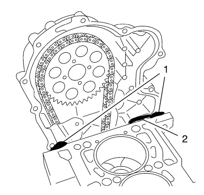
| 15. |
Fit the NEW oil pump housing
gasket (1) to the contact surface between the cylinder block and
the timing case until the seal lies flush on the cylinder block and
timing case (arrows) and the holes in the gasket and the timing
case match up. |
| 16. |
Clean all sealing
surfaces. |
|
Note: If the sealing
tab (2) is damaged, remove this with a suitable cutter and apply
sealant to the timing case contact surface!
|
| 17. |
Apply silicone sealing
compound to the transitions between the cylinder block and oil pump
housing (1). |
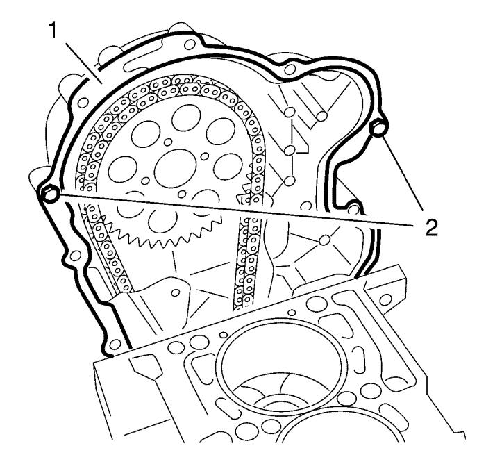
| 18. |
Fit the timing case gasket
(1). |
| |
18.1 |
Place the NEW oil pump housing
gasket (1) on the oil pump housing. |
|
Note: The bolts must be
inserted in the bores shown above the cylinder head.
|
| |
18.2 |
Loosely install the 2 bolts
(2) to fix the camshaft housing gasket. |

| 19. |
Apply silicone sealing
compound to the transitions between the engine block and oil pump
housing (1). |
| 20. |
Install the NEW cylinder head
gasket. |
| 21. |
Apply silicone sealing
compound to the transitions between the cylinder head gasket and
oil pump housing. |
| 22. |
Install the cylinder head
(2). |
| 23. |
Loosely install the 10 NEW
cylinder head bolts (1) |
| |
Carefully align the cylinder head to the timing case, using a
rubber mallet. |
|
Note: Do NOT tighten
the bolts.
|
| 24. |
Install the 3 oil pump housing
bolts to the cylinder head. |
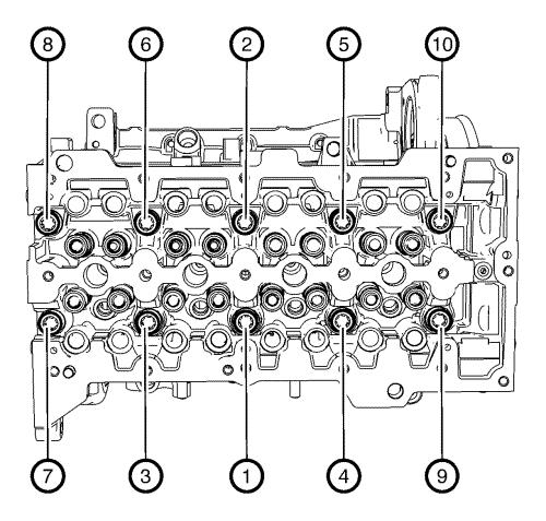
| 25. |
Tighten the 10 cylinder head
bolts in sequence as shown and in the following order: |
| |
25.1 |
Tighten the bolts in sequence
as shown to 40 N·m (30 lb ft) .
|
| |
25.2 |
Tighten in sequence as shown
to an additional 90° . Use the
EN-470-B anglemeter . |
| |
25.3 |
Tighten in sequence as shown
to an additional 90° . Use the
EN-470-B anglemeter . |
|
Note: Place clean
rags (2) in the opening to prevent the bolt from falling into the
timing case.
|
| 26. |
Install upper timing chain
guide bolt (1) and tighten to 9 N·m (80 lb
in) . |
| 27. |
Remove the clean rags
(2). |
| 28. |
Install the charge air cooler
inlet air pipe gasket (2). |
| 29. |
Install the charge air cooler
inlet air pipe (4) from the turbocharger (1). |
| 30. |
Install the 2 charge air
cooler inlet air pipe bolts (3) and tighten to 10
N·m (89 lb in) . |
| 31. |
Install the turbocharger oil
return hose (2) to the turbocharger (1) and the oil filter housing
(4). |
| 32. |
Install the 2 turbocharger oil
return hose clamps (3). |
| 33. |
Install the turbocharger oil
feed pipe (4). |
| 34. |
Install the 2 NEW turbocharger
oil feed pipe gasket (6). |
| 35. |
Install the turbocharger oil
feed pipe bolt (5) to the oil filter housing (7) and tighten to
22 N·m (16 lb ft) . |
| 36. |
Install the 2 NEW turbocharger
oil feed pipe gasket (3). |
| 37. |
Install the turbocharger oil
feed pipe bolt (2) to the turbocharger (1) and tighten to
22 N·m (16 lb ft) . |
| 38. |
Install the heater inlet hose
(1) to the exhaust gas recirculation valve cooler (2). |
| 39. |
Install the heater outlet hose
clamp (4). |
| 40. |
Clip in the heater inlet hose
(1) to the heater outlet hose (3). |
| 41. |
Install the throttle body
support (1). |
| 42. |
Install the 2 throttle body
support bolts (2) and tighten to 9 N·m (80 lb
in) . |
| 43. |
Install the NEW exhaust gas
recirculation pipe gasket (4) to the exhaust gas recirculation
pipe. |
| 44. |
Install the exhaust gas
recirculation pipe seal (2) to the exhaust gas recirculation
pipe. |
| 45. |
Install the exhaust gas
recirculation pipe (3). |
| 46. |
Install the 3 exhaust gas
recirculation pipe bolts (5) to the exhaust manifold and tighten to
9 N·m (80 lb in) . |
| 47. |
Install the 2 exhaust gas
recirculation pipe bolts (1) to the exhaust gas recirculation valve
cooler and tighten to 25 N·m (18 lb ft)
. |
| 48. |
Install the exhaust pressure
pipe (4). |
| 49. |
Install the exhaust pressure
pipe bolt (3) to the exhaust pressure sensor bracket (1) and
tighten to 9 N·m (80 lb in) . |
| 50. |
Install the exhaust pressure
pipe bolt (5) to the throttle body support and tighten to 9
N·m (80 lb in) . |
| 51. |
Install the 2 exhaust pressure
pipe clamps (2, 6). |
| 52. |
Clip in the vacuum hose to
exhaust pressure pipe (4). |
|
|
11 Engine
