
Engine block
- Make
- Volvo
- Model
- S80 Factory Service Manual
- Year
- 1999–2006
- Section
- 09 Miscellaneous › Design and Function › Engine block
Engine block
Main components
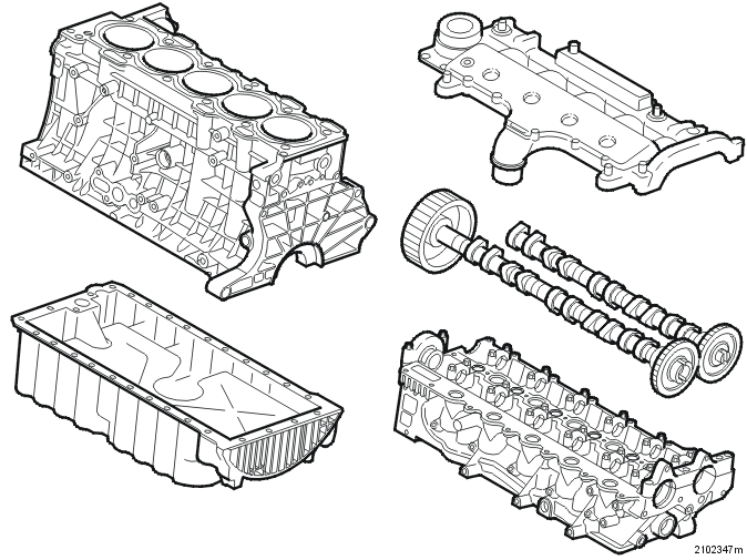
Cylinder head
- Chill cast aluminum alloy
- Double overhead camshafts
- The crankshaft uses a toothed belt to drive the intake camshaft. Mechanical adjustment of the belt tension
- The intake camshaft uses a gear drive to drive the exhaust camshaft
- The camshafts are carried directly in the cylinder head. The bearing caps are loose.
Cylinder block
- Pressed aluminum alloy
- Cast cylinder sleeves
- Open coolant mantle (the coolant flows freely around the upper section of the cylinders).
Intermediate section
- Aluminum alloy
- Functions as a cover for the crankshaft.
Oil pan
- Aluminum alloy.
Cylinder head
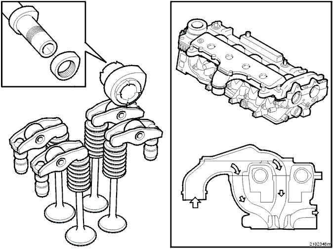
- Four valves per cylinder
- Two separate intake ports per cylinder. The length and geometry of the ports are different
- The camshafts work the valves via roller type cam followers. This design reduces friction
- Hydraulic adjustment of valve clearance
- Injector nozzle positioned in the center of the combustion chamber
- Glow plugs installed at a 30° angle.
Camshafts
- The camshafts are made up of separate components. The cam lobes and gear etc. are manufactured separately and then pressed onto a hollow shaft
- In comparison to traditionally manufactured camshafts: lighter, different types of materials can be used and the manufacturing costs are lower.
Intake camshaft
- Drives the low / high pressure pump directly via a coupling (Oldham coupling).
Exhaust camshaft
- Drives the vacuum pump.
Hydraulic adjustment of valve clearance
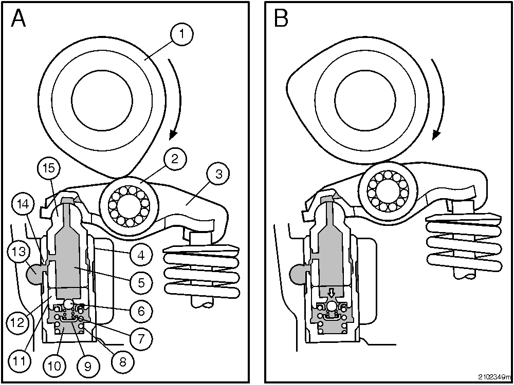
| 1 | Camshaft | 9 | Holder for the check valve spring |
| 2 | Roller | 10 | High pressure chamber |
| 3 | Roller type cam follower | 11 | Oil gallery |
| 4 | Outer housing | 12 | Plunger |
| 5 | Inner oil reservoir | 13 | Oil inlet |
| 6 | Check valve | 14 | Intake |
| 7 | Spring, check valve | 15 | Hydraulic support |
| 8 | Spring between housing and plunger |
The valve system utilizes hydraulic adjustment of the valve clearance. The advantages of this are:
- Maintenance free
- No valve train noise.
Function
The camshaft opens the valves
There must be a certain amount of internal leakage in the hydraulic unit to compensate for the expansion of the valve train during the warm up engine phase and to prevent the unit from pumping itself up at high engine speed which would result in poor valve sealing.
The following happens when the camshaft opens a valve:
- The hydraulic support and thereby the plunger are subjected to the force of the valve spring
- The distance between the plunger and the outer housing reduces
- Oil is forced from the high pressure chamber through the oil gallery and is returned to the oil reservoir
- The plunger sinks in relation to the outer housing
- During the entire opening phase of the valve the plunger continues to sink which means that the effective lift of the valve reduces in relation to the opening profile of the camshaft.
Valve closed
Compensation of the play between the camshaft and the roller type cam follower:
- The spring presses the housing and plunger apart until its camshaft and the roller type cam follower are in contact
- When the pressure in the pressure chamber is lower than that in the reservoir the check valve opens
- Oil flows from the reservoir via the check valve and fills the pressure chamber
- The check valve closes the next time the camshaft opens the valve. The pressure in the pressure chamber then exceeds that of the reservoir.
Pistons, connecting rods and the crankshaft
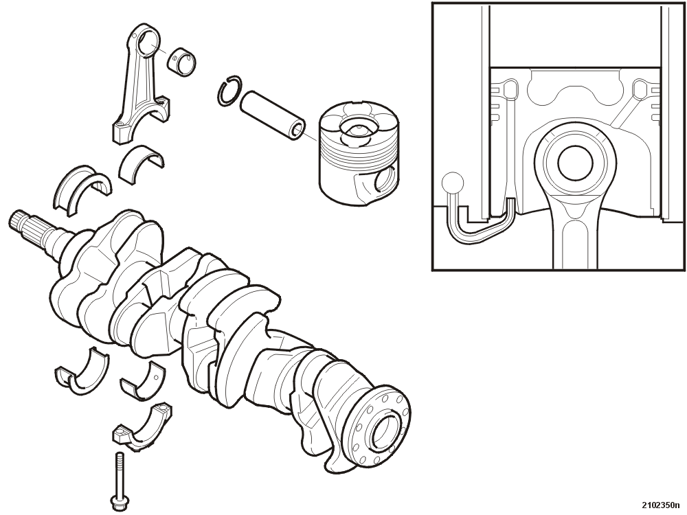
Pistons
The pistons are manufactured from an light-alloy metal consisting of aluminum and silicon. The piston skirt is graphite coated to ensure low friction between the piston and cylinder, particularly during the running-in period, during cold starting and during short periods of extreme load.
The piston is shaped for the combustion chamber, with a "ball" in the center of the top of the piston. This is used to achieve favorable swirl development. This in turn has a major impact on the combustion process.
The top ring is a forged steel ring carrier recessed in the piston. The role of this ring is to act as a wear guard for the upper piston ring and, by using an inner channel, to lead oil around the top of the piston, thereby reducing the heat generated. The oil is recirculated through a channel and sprayed on the small end of the connecting rod to lubricate the piston bolt.
The piston has three piston rings:
- The upper compression ring is made from alloyed cast iron. The surface is coated with a galvanized chrome / ceramic mixture to improve resistance to pressure, temperature and chemical reaction as well as improving the lubricating properties
- The 2nd ring is made of alloyed cast iron. Functions as both a compression ring and an oil scraper ring
- The oil control ring is made of cast iron with an internal expansion spring.
Connecting rods
The connecting rods are forged from steel and have an l-profile.
The piston bolt end is trapezium shaped, giving greater surface for the piston to transfer power on. This reduces the load on the surface unit.
The big end has a split bearing cap. This gives a stable joint because the bearing cap and connecting rod are secured in the actual fracture surface.
The lower and upper halves of the bearings for the connecting rods are different. This is due to the higher stresses that the upper bearing shell is exposed to.
- The upper half of the bearing is what is known as a Sputter bearing. The bearing consists of a steel base coated with a layer of bronze and then a thin but extremely hard aluminum layer (Sputter layer). This type of bearing can tolerate extremely high loads
- The lower half of the bearing is what is known as a lead bronze bearing. The base (steel and bronze) is the same as the Sputter bearings while the outer layer consists mainly of lead.
Crankshaft
The crankshaft is made of forged steel.
The upper and lower halves of the main bearings are different. The lower half of the bearing is exposed to greater loads than the upper.
- The upper half of the bearing is an aluminum bearing. A steel base coated with only aluminum
- The lower half of the bearing is a lead bronze bearing.
Parts & tools for this job For 1999 Volvo S80
- PARTEngine gasket setSearch: Volvo S80 1999 engine gasket set
- TOOLTorque wrenchSearch: 3/8 inch torque wrench
- TOOLFeeler gauge setSearch: feeler gauge set
Links open Amazon search results in a new tab. As an Amazon Associate I earn from qualifying purchases.