
Immobilizer – Design
- Make
- Volvo
- Model
- S80 Factory Service Manual
- Year
- 1999–2006
- Section
- 09 Miscellaneous › Design and Function › Immobilizer – Design
Immobilizer – Design
General
The security system in the vehicle is a distributed system which is monitored by the central electronic module (CEM). A number of other units and components are involved for the various functions.
Central Electronic Module (CEM)
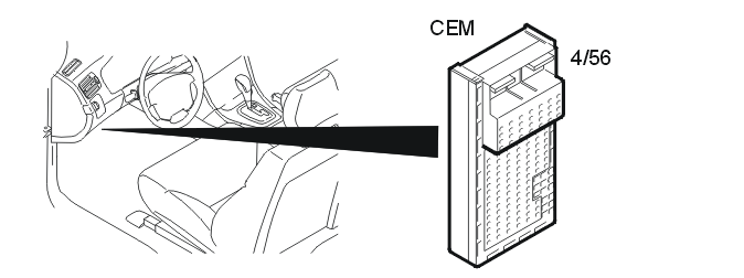
The central electronic module (CEM) (4/56) is the master unit for the immobilizer function. The central electronic module (CEM) and engine control module (ECM) are linked to each other through codes. The central electronic module (CEM) is also programmed with a code for each ignition key for the vehicle.
The central electronic module (CEM) transmits commands and signals to the other units in the system. The central electronic module (CEM) also approves the identity of the key. The key is checked via the antenna ring. The antenna ring is installed around the ignition switch. There is a transponder (communication circuit) in the ignition key. The identification code of the transponder is unique. The code must be learned by the central electronic module (CEM) before the key can be used to start the vehicle. This code is learned during at the factory. New keys can be added afterwards.
The central electronic module (CEM) checks the relay for the starter motor.
For further information about the central electronic module (CEM), see Design and Function, central electronic module (CEM).
Antenna ring
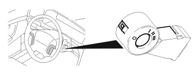
The antenna ring (16/65) is installed around the ignition switch. The antenna ring is used to allow the central electronic module (CEM) to communicate remotely with the ignition key.
The antenna ring comprises a modulation circuit and a communication circuit. The modulation circuit converts signals between the central electronic module (CEM) and the communication circuit. The communication circuit is used to communicate with the key.
When the central electronic module (CEM) activates the antenna ring, a magnetic field is generated around the antenna ring. This magnetic field is converted in the key to an electrical current, which means that the key does not require further electrical supply.
Ignition key
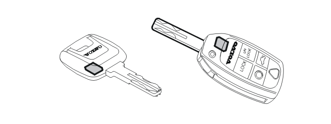
There is a communication circuit in the ignition key, known as a transponder. This circuit is supplied with power from the magnetic field that is formed around the antenna ring when the central electronic module (CEM) activates the antenna ring. Consequently, the transponder is not dependent on a further power supply.
In order for the key to be used in the vehicle, a code in the key must be entered by the central electronic module (CEM). When the vehicle is delivered from the factory, two keys are normally programmed. When a key has been programmed for the central electronic module (CEM), the key is locked and cannot be programmed for another vehicle.
Engine Control Module (ECM)
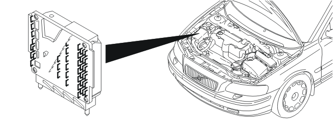
Engine control module (ECM) (4/46) checks the ignition system in the vehicle. The engine control module (ECM) also grants permission to the central electronic module (CEM) if the starter motor is to be allowed to operate when attempting to start. The functions are activated after an approved check of the ignition key has been carried out and an approved identity check has been performed between the engine control module (ECM) and the central electronic module (CEM).
In order for the engine control module (ECM) to work in the immobilizer system, the control module must be programmed with codes. This takes place the first time during installation at the factory, and then if the control module is replaced (when downloading software).
For further information, see Design and Function, engine control module (ECM).
Driver Information Module (DIM)
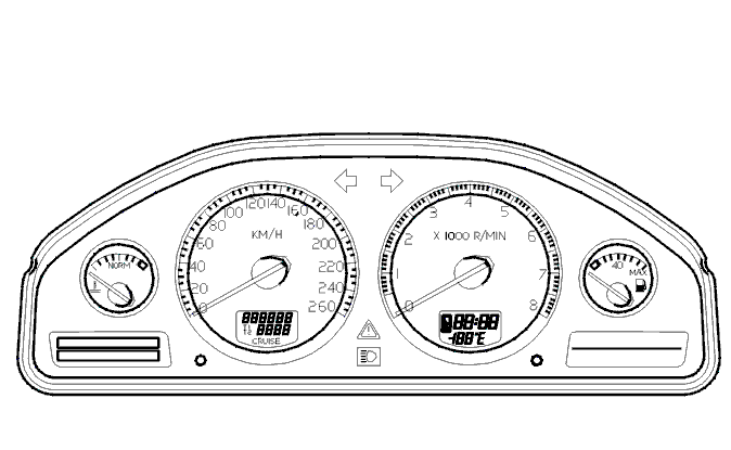
The driver information module (DIM) (5/1) receives information from the central electronic module (CEM) about which message is to appear in the display. A message will be displayed if there is a fault in any of the checks run by the system.
NOTE: There are rare cases of faults related to the immobiliser system that do not store any diagnostic trouble codes, no diagnostic trouble code appears in the Driver Information Module (DIM) either.
For further information, see Design and Function, driver information module (DIM).
General
The security system in the vehicle is a distributed system which is monitored by the central electronic module (CEM). A number of other units and components are involved for the various functions.
Central electronic module (CEM)
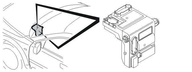
The central electronic module (CEM) (4/56) is the master unit for the immobilizer function. The central electronic module (CEM) and engine control module (ECM) are linked to each other through codes. The central electronic module (CEM) is also programmed with a code for each ignition key for the vehicle.
The central electronic module (CEM) transmits commands and signals to the other units in the system. The central electronic module (CEM) also approves the identity of the key. The key is checked via the antenna ring. The antenna ring is installed around the ignition switch. There is a transponder (communication circuit) in the ignition key. The identification code of the transponder is unique. The code must be learned by the central electronic module (CEM) before the key can be used to start the vehicle. This code is learned during installation at the factory. New keys can be added afterwards.
The central electronic module (CEM) controls the relay for the fuel pump and the relay for the starter motor (not applicable to B8444S).
For further information about the central electronic module (CEM), see Design and Function, central electronic module (CEM).
Antenna ring
The antenna ring (16/65) is installed around the ignition switch. The antenna ring is used to allow the central electronic module (CEM) to communicate remotely with the ignition key.
The antenna ring comprises a modulation circuit and a communication circuit. The modulation circuit converts signals between the central electronic module (CEM) and the communication circuit. The communication circuit is used to communicate with the key.
When the central electronic module (CEM) activates the antenna ring, a magnetic field is generated around the antenna ring. This magnetic field is converted in the key to an electrical current, which means that the key does not require further electrical supply.
Ignition key
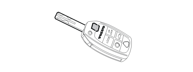
There is a communication circuit in the ignition key, known as a transponder. This circuit is supplied with power from the magnetic field that is formed around the antenna ring when the central electronic module (CEM) activates the antenna ring. Consequently, the transponder is not dependent on a further power supply.
In order for the key to be used in the vehicle, a code in the key must be entered by the central electronic module (CEM). When the vehicle is delivered from the factory, two keys are normally programmed. When a key has been programmed for the central electronic module (CEM), the key is locked and cannot be programmed for another vehicle.
Engine control module (ECM)
The engine control module (ECM) (4/46) controls the ignition system in the vehicle and controls activation of the starter motor via the starter motor relay (applicable to B8444S only). The engine control module (ECM) also grants permission to the central electronic module (CEM), indicating whether the fuel pump is permitted to run when ignition is attempted. These functions are activated once an approved check of the ignition key has been carried out and an identity check has been carried out between the engine control module (ECM) and the central electronic module (CEM) and the result approved.
In order for the engine control module (ECM) to work in the immobilizer system, the control module must be programmed with codes. This takes place for the first time during assembly in the factory, and subsequently takes place in the event the control module is replaced (when downloading software).
For further information, see Design and Function, engine control module (ECM).
Driver information module (DIM)
The driver information module (DIM) (5/1) receives information from the central electronic module (CEM) about which message is to appear in the display. A message will be displayed if there is a fault in any of the checks run by the system.
For further information, see Design and Function, driver information module (DIM).
Parts & tools for this job For 1999 Volvo S80
- TOOLTorque wrenchSearch: 3/8 inch torque wrench
- TOOLSocket setSearch: socket set metric
- BOOKHaynes manualSearch: Haynes manual Volvo S80
Links open Amazon search results in a new tab. As an Amazon Associate I earn from qualifying purchases.