Astra J
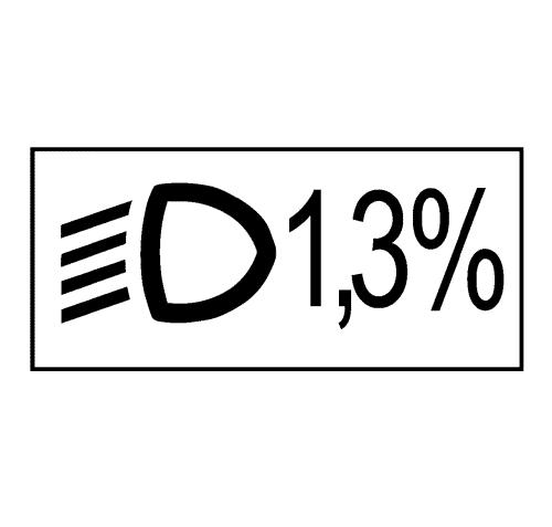
Headlamp Aiming (Regular Adjustment)Directive 76/756 EEC and ECE-Regulation 48 cover checking and aiming of headlamps on vehicle. Correct aiming of headlamps of vehicles should enable optimal road illumination by the low beam-, with minimal glare to oncoming traffic. For this purpose the inclination of the light beam in relation to the road surface and the angle of the beam to the vertical longitudinal plane running through the vehicle centre must comply with the requirements laid down in the ECE regulation and EEC directive. Glaring of the low beam is considered eliminated if the intensity of the illumination at a distance of 25 m (82 ft) from each individual headlamp on the plane perpendicular to the road and at the height of the headlamp as well as above, is not greater than 1 lux. This requirement is generally satisfied if the headlamp aiming is carried out according to these aiming guidelines. Main headlamp housing or retainer displays typically reference a 1.0 percent downward inclination for low beam aiming according to EEC 76/756 or ECE-R48 requirements. Example for a display on a headlamp with a 1.3% downward inclination for low beam aiming:
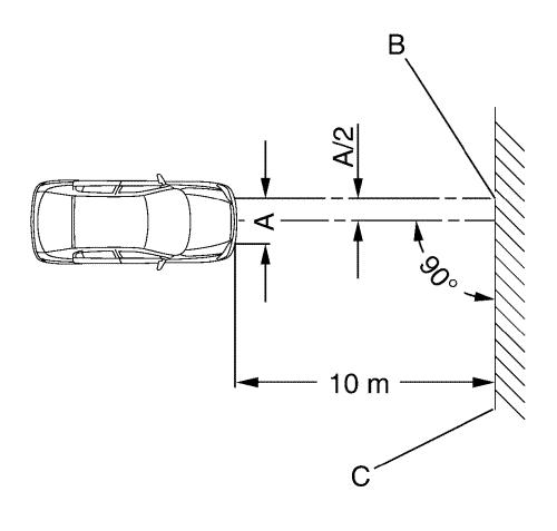
Reference 1.0 percent corresponds to the adjustment dimension of the headlamp with reference to the inclination of the light beam. The inclination at a distance of 10 m (33 ft) from vehicle headlamp is therefore 10 cm (4 in) . The inclination of the low beam headlamp is indicated by its light/dark boundary (cut-off line). The aiming guideline is shown by the following three illustrations.
Abbreviations used: A = Horizontal distance between headlamp centres B = Central marking C = Test surface
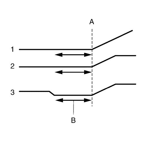
x = Kink of cut-off line for the left/right setting y = Horizontal area of the cut-off line for up/down setting 1 = Halogen 2 = Xenon 3 = AFL+
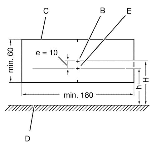
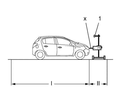
C = Test surface D = Road surface E = Break point (kink of cut-off line) e = Aiming dimension in cm, e = H – h (aiming dimension, low beam headlamps usually at 1.0 percent, e = 10 cm (4 in), front fog lamps 2.0 percent, e = 20 cm (8 in), high beam headlamps (if separately amiable) at 0 percent, e = 0 cm (0 in). H = Height of centre of headlamp over road surface h = Height of light/dark boundary line (cut-off line) of low beam above road surface The headlamp aiming is performed according to the specifications, as shown in the illustrations, using an adjuster. When using a headlamp adjuster, set up the height and position of the adjuster according to the instructions in the operation manual. Ensure that the vehicle tire surface that is in contact with the road and the surface for setting up the adjuster are at the same level and parallel with each another.
X = Center of adjuster lens (see arrow mark on adjuster housing) must be aligned on the same level as the low beam headlamp and must be parallel to the ground. 1 = Use marking of the control mirror (1) to align the adjuster system in the correct angle to the vehicle, based on the information shown in the owner operating instructions. The distance between the adjuster lens and the headlamp must be within 0,5 and 0,8 meters (refer to operation instructions of the adjuster system) The surface on which the measuring instrument (adjuster system) and the vehicle stand must be flat. The level of the ground must not vary by more than ± 0.5 mm / m .
Vehicle tires must have specified air pressure. Blackened bulbs must be replaced before adjusting. The adjustment is performed at vehicle curb weight plus one person or 75 kg (165 lb) on the driver's seat. (Curb weight = weight of vehicle ready for use with completely filled fuel tank plus the weight of all equipment carried during use, e.g. spare wheel, tools, jack, first aid kit, emergency warning triangle, etc.). For vehicle with a manual headlamp leveling system switch the ignition on and position the adjuster wheel of the manual headlamp range control at the light switch centre to "0". The intersection between the horizontal and the ascending parts of the cut-off line (break point) must lie on the perpendicular through the central marking. For easier determination of the intersection point, headlamp halves can be alternately covered and uncovered. The headlamp adjusting equipment used must comply with the existing guidelines and the manufacturer's operating instructions must be observed. The headlamp adjuster must be regularly checked by manufacturer's maintenance service.
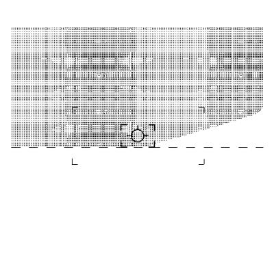
Example of a halogen low beam light pattern on a headlamp adjuster screen. Refer to the operating manual of the adjuster system. The headlamp adjuster is set up according to manufacturer's guidelines and is adjusted to 1.0 percent downwards inclination for the low beam or 2.0 percent inclination for the fog lamp or 0% for the high beam (if separately amiable). If not advised differently on the headlamp. According to the directive 76/756/EEC the 15 degree line is no longer required for the low beam on the measurement screen. The adjustment direction can also be undertaken with headlamp aiming equipment which shows the 15 degree line on the measurement screen (For all headlamps). Depending on the specific inner design of the headlamps, the movement of the lightbeam on the measurement screen is not exactly vertical or horizontal during the aiming on the aiming screws. This is caused by the technical solution of the suspension of the reflectors in the headlamp housing. After aiming of one axis the aiming of the other axis should be rechecked. For instance the vertical aiming could be changed a bit after the aiming of the horizontal axis. Therefore the vertical axis must be checked and if necessary aimed again after the aiming of the horizontal axis. If a headlamp shows a significant deviation from the correct aiming for both horizontal and vertical direction the aiming operation must be performed step by step for the two directions. This means that in such a case the aiming of horizontal and vertical direction must be done alternately in small steps. Not more than one turn of an aiming screw shall be performed at once. After one turn change to the other aiming screw. Repeat this procedure until the headlamp is correctly aimed.
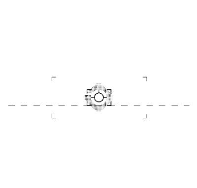
Example of a high beam light pattern on a headlamp adjuster screen. Refer to the operating manual of the adjuster system. In headlamps where the high and low beam can be aimed, the centre of the high beam must lie within the boundary corners around the central mark.
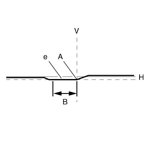
Turn headlamp switch into position II (low beam) A= Break point for the side setting in line V B= Setting of the height by means of cut-off line in this area usually at 1 percent (e = 10 cm or 4 in) downward inclination. e = Aiming dimension.
Headlamps must be aimed using a legally specified projection wall or with optical headlamp adjuster. For the vertical aiming (adjustment of height) the cut-off line on the left side of the adjustment cross must be parallel to the horizontal adjustment line. Note: Carry out vertical aiming first, then lateral aiming. Check vertical aiming again after lateral aiming. For the horizontal aiming (adjustment of the side) the cut-off line must be horizontal on the left side of the adjustment cross and rising upward on the right side of the adjustment cross. The downward inclination is typically 1.0 percent. Note: This description is valid for right hand traffic. For left hand traffic the light pattern of left and right side is mirrored. Note: DO NOT aim the headlamps when the headlamp switch is on position “AUTO” and the engine is running. In this case the headlamps turn for 8° outward to go into the play street mode. The reference run must be performed for each single headlamp after aiming. During the reference run check for enough clearance between the projector module and the reflector and that the module bezel is free from scratches. In case of a touch condition between the projector module and bezel during the reference run or visible scratches on the bezel the headlamp aiming must be checked again. Conditions like these occur if the aiming differs extremely from the set position. |
||||||||||||||||||||||||||||||||||||||||||||