
Functional Description
- Make
- Alfa Romeo
- Model
- 145/146 Electrical System Diagnosis Manual, Volume 3
- Year
- 1994–2001
- Section
- Instrument Cluster › Functional Description
145 electrical system diagnosisFunctional Description
Functional Description
The instrument cluster is supplied by direct voltage via fuse F16 and with "key-operated" voltage via fuse F15 of fusebox G1.
For box "C" there is fuse G395 next to it. Connection is made respectively at pin 1 and 2 of connector B of the cluster C10.
Connection takes place respectively at pins 1 and 2 of connector B of the cluster C10.
The cluster C10 is connected to earth by the cable that leaves pin 13 of connector A towards earth G53b.
Components and Connectors
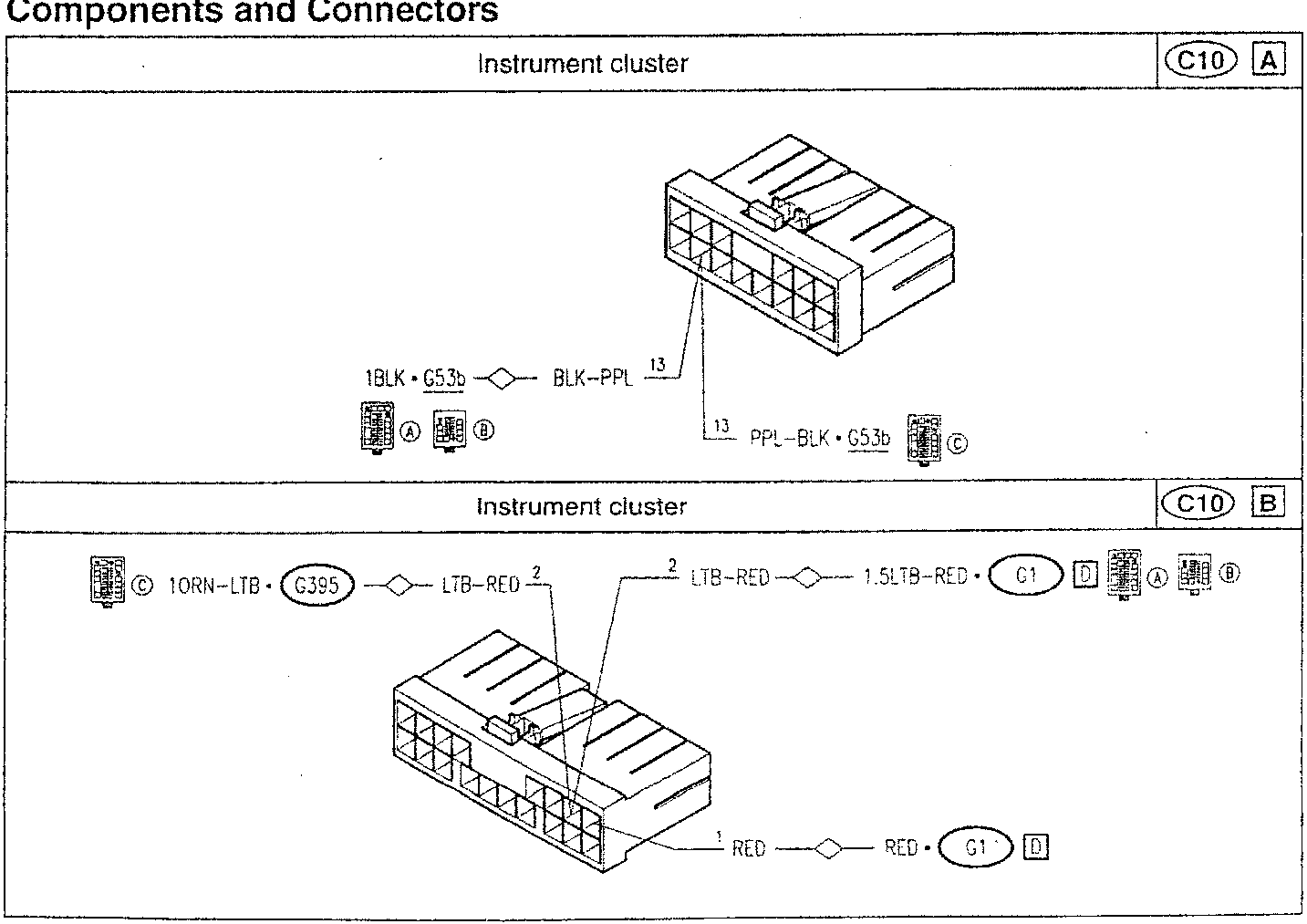
Instrument cluster
- 1BLK • G53b — BLK–PPL 13
- PPL–BLK • G53b
Instrument cluster
- 10RN–LTB • G395 — LTB–RED 2
- LTB–RED — 1.5LTB–RED • G1
- RED — RED • G1
Parts & tools for this job For 1994 Alfa Romeo 145/146
- TOOLDigital multimeterSearch: automotive digital multimeter
- PARTAssorted fuse kitSearch: car fuse assortment kit
- TOOLWire crimper and connector kitSearch: wire crimper connector kit
Links open Amazon search results in a new tab. As an Amazon Associate I earn from qualifying purchases.