
General description
- Make
- Alfa Romeo
- Model
- 145/146 Electrical System Diagnosis Manual, Volume 3
- Year
- 1994–2001
- Section
- Instrument Cluster › General description
GENERAL DESCRIPTION
The instrument cluster offers all the indications and information about the conditions of the vehicle which are indispensable for safe and troublefree driving. The cluster is of the analogue type with two large dials for the speedometer and rev counter, plus other gauges for the fuel level and coolant temperature. A comprehensive set of plainly visible warning lights completes the information for the driver.
N.B.: The instrument cluster is made as a single component: all the internal connections are made on a printed circuit which brings together the contacts of the instruments and of the various warning lights. Therefore, repair operations are not possible, not even the changing of a warning light bulb.
Note: the section has been subdivided into 5 wiring diagrams:
- – the first diagram considers all the internal connections of the printed circuit.
– the following 4 diagrams describe certain specific functions: here, only those functions that do not appear elsewhere are described and only with regard to the instrument cluster; other functions, such as warning lights, are included in the wiring diagram of the unit or system to which they refer: for example the high beam headlamp warning light is included in the diagram "High beam and low beam headlamps", etc...
N.B.: the first diagram shows the connections which supply the instrument cluster ( [symbol] or [symbol] ) and earth ( [symbol] ); in the subsequent diagrams these lines are no longer shown, but this connection is indicated by the corresponding symbols, and may at all events be checked in the internal diagram.
The instrument cluster lighting, supplied when the sidelights are turned on, is described separately (see Lighting of controls and indicators")
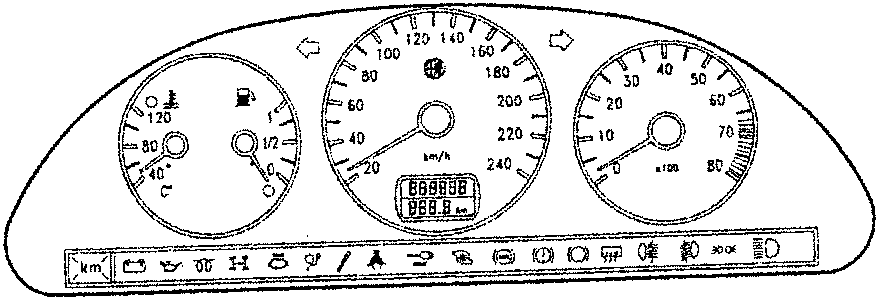
(*) from Model Year '97
(**) from Model Year '99
INTERNAL WIRING DIAGRAM (printed circuit)
Functional description
This wiring diagram represents the printed circuit and the connections inside the instrument cluster C10. shown, while this diagram gives an overall view of the entire instrument cluster C10. the other diagrams concerning the outside connections of the cluster, only the lines concerned are shown, while this diagram gives an overall view of the entire instrument cluster C10.
NOTE: not all the output pins are connected for all the versions of the car: some lines in this diagram therefore might not be used (e.g. warning lights not connected) but they are still present on the printed circuit, which is the same for all versions.
Parts & tools for this job For 1994 Alfa Romeo 145/146
- TOOLDigital multimeterSearch: automotive digital multimeter
- PARTAssorted fuse kitSearch: car fuse assortment kit
- TOOLWire crimper and connector kitSearch: wire crimper connector kit
Links open Amazon search results in a new tab. As an Amazon Associate I earn from qualifying purchases.