
R cylinder head - overhaul
- Make
- Alfa Romeo
- Model
- 147 Factory Service Manual
- Year
- 2000–2004
- Section
- Cylinder head/s › R cylinder head - overhaul
R cylinder head - overhaul
Dismantling
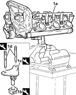
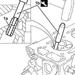
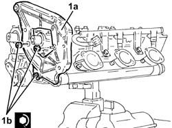
1. Position the cylinder head (1a) in the vice, using tools (1b), 1 (c) and 1(d).
| Name | Country | |
|---|---|---|
| 1b | Mount | 1.820.012.000 |
| Name | Country | |
|---|---|---|
| 1c | Mount | 1.820.050.000 |
| Name | Country | |
|---|---|---|
| 1d | 1.860.952.000 |
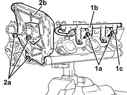
1. Undo the bolts (1a) and remove the fuel manifold (1b), complete with injectors (1c).
2. Undo the nuts (2a) and remove the bracket on the engine for the reaction rod (2b).
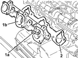
1. Undo the bolts (1a) and remove the inlet manifold (1b).
2. Remove the gasket.
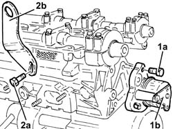
1. Undo the bolts (1a) and remove the moving timing belt tensioner (1b).
2. Undo the bolt (2a) and remove the bracket (2b).
Check that the camshaft end float is within the recommended values using a dial gauge on a magnetic base.
| Measurement | Value | ||
|---|---|---|---|
| Camshaft end float (mm) | 0.060 ÷ 0.201 |
If the value of the camshaft end float is not within the recommended values, when reassembling, replace the worn components.
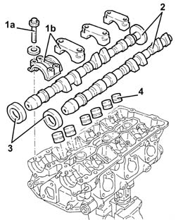
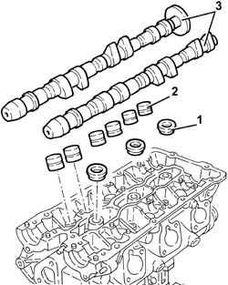
1. Undo the bolts (1a) and remove the camshaft caps (1b).
2. Remove the camshafts.
3. Remove the front camshaft oil seals.
4. Remove the hydraulic tappets.
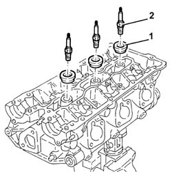
1. Remove the spark plug housing gaskets.
2. Remove the spark plugs.
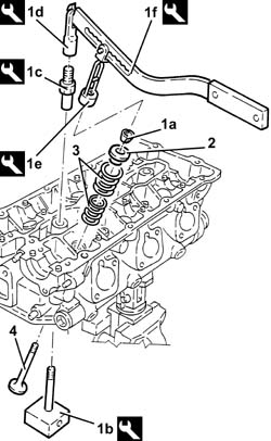
1. Remove the split collars (1a) for the cylinder in question using tools (1b), (1c), (1d), (1e) and (1f).
| Name | Country | |
|---|---|---|
| 1b | Valve supports | 1.820.011.000 |
| Name | Country | |
|---|---|---|
| 1c | Special nut | 1.820.049.000 |
| Name | Country | |
|---|---|---|
| 1d | Mount | 1.821.124.000 |
| Name | Country | |
|---|---|---|
| 1e | Chamber | 1.821.205.000 |
| Name | Country | |
|---|---|---|
| 1f | Lever | 1.821.058.000 |
2. Remove the upper valve shims.
3. Remove the valve springs.
Remove the tools used for dismantling the valves.
4. Remove the valves.
Work in the same way to remove the remaining valves.
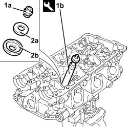
1. Remove the valve guide oil seals (1a) using the tool (1b).
| Name | Country | |
|---|---|---|
| 1b | Extractor | 1.821.208.000 |
2. Remove the lower spring washers (2a) and the lower valve shims (2b).
Remove the cylinder head from the supporting tools and position it on an appropriate workbench.
1. Remove valve guides (1a) using tool (1b).
| Name | Country | |
|---|---|---|
| 1b | Extractor | 1.821.176.000 |
Reassembling
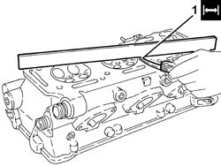
Clean the residues of the old gasket from the lower surface of the cylinder head.
1. Check that the planarity of the lower cylinder head surface is within the recommended values.
If necessary, both cylinder heads should be refaced.
| Measurement | Value | ||
|---|---|---|---|
| 1 | Cylinder head lower plane planarity (mm) | < 0.1 |
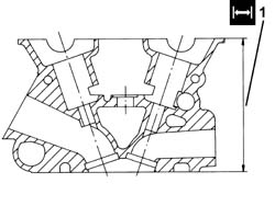
1. If the planarity of the lower cylinder head surface is not within the recommended values, reface the lower cylinder head surface without exceeding the minimum permissible height.
The minimum permitted cylinder head height should never be exceeded, or else the actual cylinder head has to be replaced.
| Measurement | Value | ||
|---|---|---|---|
| 1 | Minimum permitted cylinder head height (mm) | 134.85 ÷ 135.15 |
De-carbonize the valves and check that the stem does not show signs of grooves or seizing.
Check that the diameter of the valve stems is within the recommended values; if this is not the case, replace the worn valves.
| Measurement | Value | ||
|---|---|---|---|
| Valve stem diameter (mm) | 6.965 ÷ 6.980 |
Check that the outer diameter of the hydraulic tappets is within the recommended values. if this is not the case, replace the worn hydraulic tappets.
| Measurement | Value | ||
|---|---|---|---|
| Hydraulic tappeter outer diameter (mm) | 32.959 ÷ 32.975 |
Check that the diameter of the tappet casing housings are within the recommended values.
| Measurement | Value | ||
|---|---|---|---|
| Diameter of hydraulic tappet seats (mm) | 33.000 - 33.025 |
Check that the length of the uncompressed valve springs is within the recommended values.
| Measurement | Value | ||
|---|---|---|---|
| Valve spring length released (mm) | External | 45.0 | |
| Internal | 42.0 | ||
Use a torque wrench to check that the spring specifications are within specified values; if this is not the case, replace parts that have yielded.
| Measurement | Value | ||
|---|---|---|---|
| Outer valve spring height (mm) | 32.5 | ||
| Check load (daN) | 21.9 ÷ 23.1 | ||
| Measurement | Value | ||
|---|---|---|---|
| Outer valve spring height (mm) | 23.0 | ||
| Check load (daN) | 43.1 ÷ 45.0 | ||
| Measurement | Value | ||
|---|---|---|---|
| Inner valve spring height (mm) | 30.5 | ||
| Check load (daN) | 12.4 ÷ 13.1 | ||
| Measurement | Value | ||
|---|---|---|---|
| Inner valve spring height (mm) | 21.0 | ||
| Check load (daN) | 24.0 ÷ 26.0 | ||
Check that the cam journal diameters are within the recommended values; if this is not the case, replace the worn camshafts.
The surfaces of the camshaft bearings should not show signs of wear, grooves or seizing or else the shafts have to be replaced.
| Measurement | Value | ||
|---|---|---|---|
| Camshaft bearing diameter (mm) | 26.959 ÷ 26.980 |
Check that the nominal lift of the camshaft cams is within the recommended values; if this is not the case, replace the worn camshafts.
The surfaces of the camshaft bearings should not show signs of wear, grooves or seizing or else the shafts have to be replaced.
| Measurement | Value | ||
|---|---|---|---|
| Camshaft nominal cam lift (mm) | 9.30 |
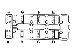
Place the camshaft caps back in their housings in the right cylinder head following the sequence shown in the diagram.
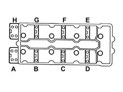
1. Tighten the camshaft cap bolts to the specified torque.
| Fastening | Component | Ø | Value (daNm) | |
|---|---|---|---|---|
| 1 | Bolt | CAMSHAFT CAPS/ | M8 | (Cylinder head side) 1.8 ÷ 2.0 |
2. Check the diameter of the camshaft mounts is within specified values.
| Measurement | Value | ||
|---|---|---|---|
| 2 | Camshaft bearing diameter (mm) | 27.010 ÷ 27.036 |
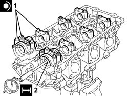
Check that the outer diameter of the valve guides is within the recommended values.
| Measurement | Value | ||
|---|---|---|---|
| Valve guide outer diameter (mm) | Intake | 12.040 ÷ 12.051 |
| Measurement | Value | ||
|---|---|---|---|
| Valve guide outer diameter oversize (mm) | Intake | 0.20 |
Inlet valve guides are available from the Parts Dept. with an outer diameter of 12.053 12.064 mm.
| Measurement | Value | ||
|---|---|---|---|
| Valve guide outer diameter (mm) | Exhaust | 12.050 ÷ 12.068 |
| Measurement | Value | ||
|---|---|---|---|
| Valve guide outer diameter oversize (mm) | Exhaust | 0.20 |
Exhaust valve guides are available from the Parts Dept. with an outer diameter of 12.064 12.082 mm.
Check that the diameter of the valve guide seat is within the recommended values. if this is not the cse, ream the seats depending on the valve guide oversize.
| Measurement | Value | ||
|---|---|---|---|
| Valve guide bore diameter (mm) | 12.000 ÷ 12.018 |
1. Place the valve guides (1a) back in their seats using the fitting tool (1b).
Using the above mentioned tool guarantees the correct valve guide projection.
| Name | Country | |
|---|---|---|
| 1b | Fitting tool | 1.821.207.000 |
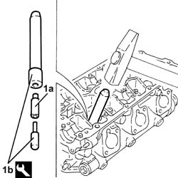
1. Ream the new valve guides using a suitable tool for calibrating the openings to the correct diameter.
| Measurement | Value | ||
|---|---|---|---|
| 1 | Valve guide internal diameter (reaming) (mm) | 7.000 ÷ 7.015 |
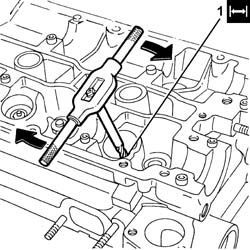
1. Regrind the valve seats to the recommended dimensions.
| Measurement | Value | ||
|---|---|---|---|
| 1 | Contact band angle with valves (-) | 90˚ ± 20∍ |
Grind the valve seats using a suitable tool.
Use SIPAL Arexons abrasive or a similar product to grind the valve seats.
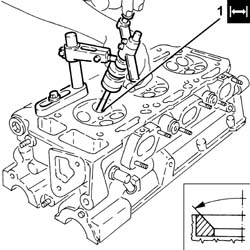
Positino the cylinder head in the vice using the tools.
| Name | Country | |
|---|---|---|
| Mount | 1.820.012.000 |
| Name | Country | |
|---|---|---|
| Mount | 1.820.050.000 |
| Name | Country | |
|---|---|---|
| 1.860.952.000 |
Place the lower valve shims and the lower spring seals back in their housings.
1. Place the valve guide oil seals (1a) back in their housings using the tool (1b).
| Name | Country | |
|---|---|---|
| 1b | Fitting tool | 1.821.206.000 |
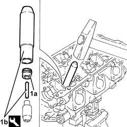
1. Place the valves (1a) for the cylinder in question back in their seats and support them using the tools (1b) and (1c).
| Name | Country | |
|---|---|---|
| 1b | Valve supports | 1.820.011.000 |
| Name | Country | |
|---|---|---|
| 1c | Special nut | 1.820.049.000 |
2. Place the valve springs back in their seats.
3. Place the upper valve shims back in their housings.
4. Place the cotters (4a) for the valves for the cylinder in question bakc in their housings using the tools (4b), (4c) and (4d).
| Name | Country | |
|---|---|---|
| 4b | Mount | 1.821.124.000 |
| Name | Country | |
|---|---|---|
| 4c | Chamber | 1.821.205.000 |
| Name | Country | |
|---|---|---|
| 4d | Lever | 1.821.058.000 |
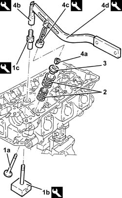
Remove the tools used for fitting valves.
Work in the same way when fitting the remaining valves.
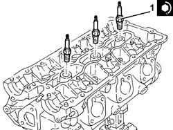
1. Place the spark plugs back in their housings and tighten them to the recommended torque.
| Fastening | Component | Ø | Value (daNm) | |
|---|---|---|---|---|
| 1 | SPARK PLUGS | M14 | (Cylinder head side) 2.4 ÷ 3.0 |
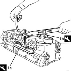
1. Carry out the valve leakage test using the tools (1a) and (1b).
| Name | Country | |
|---|---|---|
| 1a | Lever | 1.860.490.000 |
| Name | Country | |
|---|---|---|
| 1b | Test instrument | 1.895.868.000 |
1. Place the spark plug housing seals back in their housings.
2. Place the hydraulic tappets in their housings.
3. Place the camshafts back in their housings.
Place the camshaft caps back in their housings in the right cylinder head following the sequence shown in the diagram.
Tighten the camshaft cap bolts to the specified torque.
| Fastening | Component | Ø | Value (daNm) | |
|---|---|---|---|---|
| Bolt | CAMSHAFT CAPS/ | M8 | (Cylinder head side) 1.8 ÷ 2.0 |
1. Fit the camshaft front oil seals (1a) using the tool (1b).
| Name | Country | |
|---|---|---|
| 1b | Fitting tool | 1.860.948.000 |
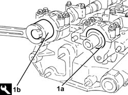
Place the bracket back in its housing and secure it using the bolt.
Fit the timing belt mobile tensioner and fix it using the bolts without tightening them.
1. Place the intake manifold (1a), complete with gasket (1b), back in its housing and secure it tightening the bolts (1c) to the recommended torque.
| Fastening | Component | Ø | Value (daNm) | |
|---|---|---|---|---|
| 1c | Bolt | INLET MANIFOLD | M8 | (Cylinder head side) 1.9 ÷ 2.3 |
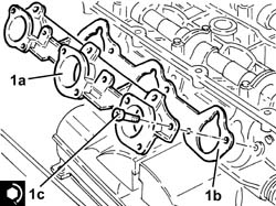
1. Fit the bracket on the engine for the reaction rod (1a) and fix it tightening the nuts (1b) to the recommended torque.
| Fastening | Component | Ø | Value (daNm) | |
|---|---|---|---|---|
| 1b | Nut | REACTION LINK BRACKET ON ENGINE | M10 | (Cylinder head side) 4.5 ÷ 5.5 |
Place the fuel manifold, complete with injectors, back in its housing and fix it using the bolts.
Remove the cylinder head from the supporting tools.
Parts & tools for this job For 2000 Alfa Romeo 147
- PARTEngine gasket setSearch: Alfa Romeo 147 2000 engine gasket set
- TOOLTorque wrenchSearch: 3/8 inch torque wrench
- TOOLFeeler gauge setSearch: feeler gauge set
Links open Amazon search results in a new tab. As an Amazon Associate I earn from qualifying purchases.