
Fuel delivery line - r r
- Make
- Alfa Romeo
- Model
- 147 Factory Service Manual
- Year
- 2000–2004
- Section
- Fuel tank and pipes › Fuel delivery line - r r
Fuel delivery line - r r
Removing
Position the vehicle on the ramp.
Ensure that the ignition key is in the OFF postition, then disconnect the battery negative terminal.
| Name | Connector | |
|---|---|---|
| Battery | A1B |
Proceed with the removal - 4450B10 Front WHEEL (one) - R.R. (Right side).
Proceed with the removal - 4450B11 WHEEL (one) rear - R.R. (Right side).
Proceed with the removal - 1016A40 ignition coil cover on cylinder head- r+r.
Drain the air conditioner refrigerant system - 5040A10 Air conditioning refrigerant CIRCUIT - Draining and Refilling.
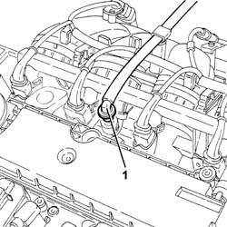
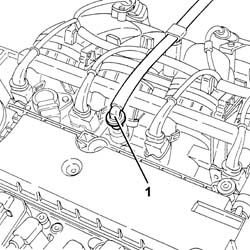
1. Disconnect the rapid attachment for the fuel supply pipe from the fuel manifold.
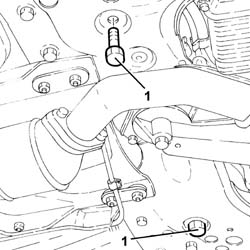
1. Undo the bolts and move the power steering box as far forward as necessary.
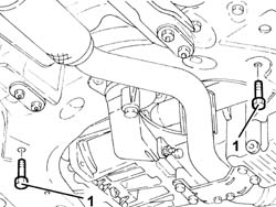
1. Undo the bolts and move the power steering box as far forward as necessary.
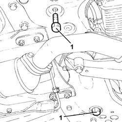
Disengage the fuel delivery pipe from the fastenings on the engine bay bulkhead.
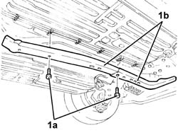
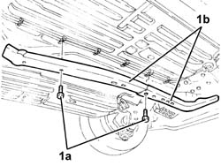
1. Undo the bolts (1a) and remove the protections (1b) for the fuel outlet pipes and fuel vapour recovery pipe.
Proceed with the removal - 1040A70 submerged pump assembly complete with level guage control - r + r.
Remove the handbrake boot.
Proceed with the removal - 1076B22 rear exhaust silencer - r+r emission control versions.
Proceed with the removal - 1076B26 intermediate exhaust silencer - r+r emission control versions.
Proceed with the removal - 1040A10 fuel tank - r + r and decant fuel.
Tighten the rear suspension beam bolts provisionally.
Remove the hydraulic jack from under the crossmember.
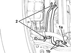
1. Undo bolt (1a) and disconnect flange (1b) of the pipe from condenser to intermediate connector, intermediate connector side.
Seal the disconnected connectors, using suitable plugs, to prevent humidity and impurities from entering the system.
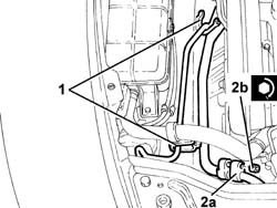
2. Release the air conditioning system hoses from the fastenings on the side panel.
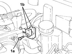
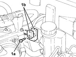
1. Undo the bolt (1a) and disconnect the supply and return pipes from the evaporator (1b), evaporator side.
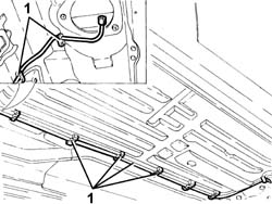
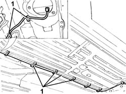
1. Release the fuel supply pipe from the fastenings under the body and remove.
Refitting
Refit the fuel supply pipe and secure it to the underbody using the appropriate fasteners.
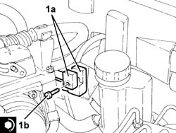
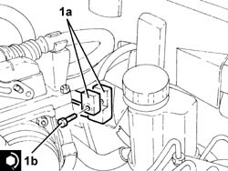
1. Connect the supply and return pipes from the evaporator (1a), evaporator side and secure them tightening the bolt (1b) to the recommended torque.
Replace the O-Ring seals for the connectors. Only use green coloured seals, resistant to R134A coolant fluid.
Lubricate the threads of the connectors using anti-freeze.
| Fastening | Component | Ø | Value (daNm) | |
|---|---|---|---|---|
| 1b | Bolt | EVAPORATOR INLET/OUTLET PIPES | M6 | (Evaporator side) 0.7 ÷ 1.1 |
1. Secure the air conditioning system pipes using the fasteners on the side panels.
2. Connect the flange of the pipe from the air conditioning condenser to the intermediate fitting (2a), intermediate connector side and tighten the nut (2b) to the recommended torque.
| Fastening | Component | Ø | Value (daNm) | |
|---|---|---|---|---|
| 2b | Nut | COOLANT SYSTEM FITTINGS | M6 | 0.7 ÷ 1.1 |
Position a hydraulic jack under the rear suspension crossmember.
Unscrew the bolts securing the rear suspension beam.
Proceed with the refitting - 1040A10 fuel tank - r + r and decant fuel.
Proceed with the refitting - 1076B26 intermediate exhaust silencer - r+r emission control versions.
Proceed with the refitting - 1076B22 rear exhaust silencer - r+r emission control versions.
Adjust the travel of the handbrake lever - 3380A04 handbrake - check travel.
Place the handbrake boot back in its housing.
Proceed with the refitting - 1040A70 submerged pump assembly complete with level guage control - r + r.
Refit the protections for the fuel outlet hose and fuel vapour recovery hose and secure with bolts.
Secure the fuel supply pipe using the fastenings in the engine compartment.
Place the power assisted steering box back in its housing and secure by tightening the bolts to the recommended torque.
| Fastening | Component | Ø | Value (daNm) | |
|---|---|---|---|---|
| Bolt | POWER STEERING BOX | M14 | (Front suspension crossmember side) 11.7 ÷ 14.3 |
Connect the rapid attachment for the fuel supply pipe to the fuel manifold.
Refill the air conditioner refrigerant system - 5040A10 Air conditioning refrigerant CIRCUIT - Draining and Refilling.
Proceed with the refitting - 1016A40 ignition coil cover on cylinder head- r+r.
Proceed with the refitting - 4450B11 WHEEL (one) rear - R.R. (Right side).
Proceed with the refitting - 4450B10 Front WHEEL (one) - R.R. (Right side).
Connect the battery terminal (-).
Remove the car from the ramp.
Removing
Position the vehicle on the ramp.
Ensure that the ignition key is in the OFF postition, then disconnect the battery negative terminal.
| Name | Connector | |
|---|---|---|
| Battery | A1B |
Proceed with the removal - 4450B10 Front WHEEL (one) - R.R. (Right side).
Proceed with the removal - 4450B11 WHEEL (one) rear - R.R. (Right side).
Proceed with the removal - 1016A40 ignition coil cover on cylinder head- r+r.
Drain the air conditioner refrigerant system - 5040A10 Air conditioning refrigerant CIRCUIT - Draining and Refilling.
1. Disconnect the rapid attachment for the fuel supply pipe from the fuel manifold.
1. Undo the bolts and move the power steering box as far forward as necessary.
Disengage the fuel delivery pipe from the fastenings on the engine bay bulkhead.
1. Undo the bolts (1a) and remove the protections (1b) for the fuel outlet pipes and fuel vapour recovery pipe.
Proceed with the removal - 1040A70 submerged pump assembly complete with level guage control - r + r.
Remove the handbrake boot.
Proceed with the removal - 1076B22 rear exhaust silencer - r+r emission control versions.
Proceed with the removal - 1076B26 intermediate exhaust silencer - r+r emission control versions.
Proceed with the removal - 1040A10 fuel tank - r + r and decant fuel.
Tighten the rear suspension beam bolts provisionally.
Remove the hydraulic jack from under the crossmember.
1. Undo bolt (1a) and disconnect flange (1b) of the pipe from condenser to intermediate connector, intermediate connector side.
Seal the disconnected connectors, using suitable plugs, to prevent humidity and impurities from entering the system.
2. Release the air conditioning system hoses from the fastenings on the side panel.
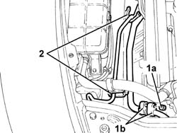
1. Undo the bolt (1a) and disconnect the supply and return pipes from the evaporator (1b), evaporator side.
1. Release the fuel supply pipe from the fastenings under the body and remove.
Refitting
Refit the fuel supply pipe and secure it to the underbody using the appropriate fasteners.
1. Connect the supply and return pipes from the evaporator (1a), evaporator side and secure them tightening the bolt (1b) to the recommended torque.
Replace the O-Ring seals for the connectors. Only use green coloured seals, resistant to R134A coolant fluid.
Lubricate the threads of the connectors using anti-freeze.
| Fastening | Component | Ø | Value (daNm) | |
|---|---|---|---|---|
| 1b | Bolt | EVAPORATOR INLET/OUTLET PIPES | M6 | (Evaporator side) 0.7 ÷ 1.1 |
1. Secure the air conditioning system pipes using the fasteners on the side panels.
2. Connect the flange of the pipe from the air conditioning condenser to the intermediate fitting (2a), intermediate connector side and tighten the nut (2b) to the recommended torque.
| Fastening | Component | Ø | Value (daNm) | |
|---|---|---|---|---|
| Nut | COOLANT SYSTEM FITTINGS | M6 | 0.7 ÷ 1.1 |
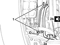
Position a hydraulic jack under the rear suspension crossmember.
Unscrew the bolts securing the rear suspension beam.
Proceed with the refitting - 1040A10 fuel tank - r + r and decant fuel.
Proceed with the refitting - 1076B26 intermediate exhaust silencer - r+r emission control versions.
Proceed with the refitting - 1076B22 rear exhaust silencer - r+r emission control versions.
Adjust the travel of the handbrake lever - 3380A04 handbrake - check travel.
Place the handbrake boot back in its housing.
Proceed with the refitting - 1040A70 submerged pump assembly complete with level guage control - r + r.
Refit the protections for the fuel outlet hose and fuel vapour recovery hose and secure with bolts.
Secure the fuel supply pipe using the fastenings in the engine compartment.
Place the power assisted steering box back in its housing and secure by tightening the bolts to the recommended torque.
| Fastening | Component | Ø | Value (daNm) | |
|---|---|---|---|---|
| Bolt | POWER STEERING BOX | M14 | (Front suspension crossmember side) 11.7 ÷ 14.3 |
Connect the rapid attachment for the fuel supply pipe to the fuel manifold.
Refill the air conditioner refrigerant system - 5040A10 Air conditioning refrigerant CIRCUIT - Draining and Refilling.
Proceed with the refitting - 1016A40 ignition coil cover on cylinder head- r+r.
Proceed with the refitting - 4450B11 WHEEL (one) rear - R.R. (Right side).
Proceed with the refitting - 4450B10 Front WHEEL (one) - R.R. (Right side).
Connect the battery terminal (-).
Remove the car from the ramp.
Parts & tools for this job For 2000 Alfa Romeo 147
- PARTFuel filterSearch: Alfa Romeo 147 2000 fuel filter
- TOOLFuel pressure test kitSearch: fuel pressure test kit
- TOOLFuel line disconnect toolSearch: fuel line disconnect tool
Links open Amazon search results in a new tab. As an Amazon Associate I earn from qualifying purchases.