
Fuel tank and components
- Make
- Alfa Romeo
- Model
- 147 Factory Service Manual
- Year
- 2000–2004
- Section
- Fuel tank and pipes › Fuel tank and components
Fuel tank and components
OPERATION
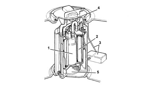
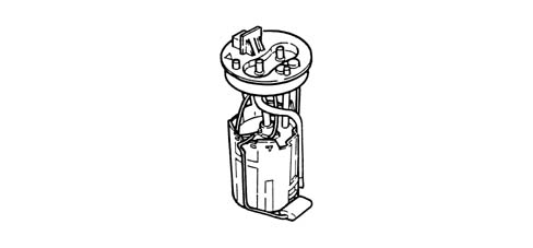
Immersed pump unit complete with fuel gauge sender unit
It mainly consists of:
- an electric fuel pump (1)
- a fuel filter (2)
- a float type fuel gauge (3)
- a diaphragm pressure regulator (4)
- a mesh pre-filter (5).
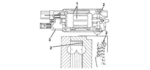
Ekp 13.5 electric fuel pump
The fuel pump comprises a permanent-magnet electric motor (1) which controls the pump impeller (2), and a terminal-carrier cover (3), which contains the electrical and hydraulic connections.
The pump stage is the single type with peripheral flow, with high performance in low voltage and temperature conditions.
Its advantages compared with pumps operating in accordance with the positive-displacement principle are:
- lightweight
- small in size.
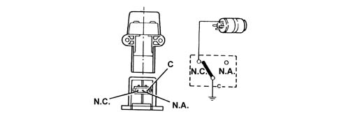
Inertia switch
The inertia switch is fitted on the driver's side near the bolt fixing the running board to the front door pillar. In the case of an impact to the vehicle, it interrupts the connection to earth for the electric fuel pump and consequently the supply of fuel to the injection system.
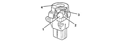
A steel ball (1) mounted in a conical housing (2) is normally locked by the attraction force of an adjacent magnet.
For specific acceleration loads, the ball is released from the magnetic clip and gradually comes out of the conical housing in an upwards movement following the angle of the cone.
Above the ball, there is a quick-trip mechanism (3) which forms the normally closed (N.C.) electric circuit.
When the mechanism is struck by the ball, it changes position from an N.C. circuit to a normally open (N.A.) circuit, eaking the fuel pump's earth circuit.
The switch can be reset by pressing a button protected by a soft cover (4).
Even after an apparently minor impact, if there is a smell of fuel or leaks are noticed from the fuel system, do not turn the switch back on, but search for the cause of the problem and remedy it to prevent the risk of fire. Otherwise, if there are no leaks and the vehicle can be restarted, press the button to reactivate the pump.
OPERATION
Immersed pump unit complete with fuel gauge sender unit
It mainly consists of:
- an electric fuel pump (1)
- a fuel filter (2)
- a float type fuel gauge (3)
- a diaphragm pressure regulator (4)
- a mesh pre-filter (5).
Ekp 13.5 electric fuel pump
The fuel pump comprises a permanent-magnet electric motor (1) which controls the pump impeller (2), and a terminal-carrier cover (3), which contains the electrical and hydraulic connections.
The pump stage is the single type with peripheral flow, with high performance in low voltage and temperature conditions.
Its advantages compared with pumps operating in accordance with the positive-displacement principle are:
- lightweight
- small in size.
Inertia switch
The inertia switch is fitted on the diver's side near the bolt fixing the running board to the front door pillar. In the case of an impact to the vehicle, it interrupts the connection to earth for the electric fuel pump and consequently the supply of fuel to the injection system.
A steel ball (1) mounted in a conical housing (2) is normally locked by the attraction force of an adjacent magnet.
For specific acceleration loads, the ball is released from the magnetic clip and gradually comes out of the conical housing in an upwards movement following the angle of the cone.
Above the ball, there is a quick-trip mechanism (3) which forms the normally closed (N.C.) electric circuit.
When the mechanism is struck by the ball, it changes position from an N.C. circuit to a normally open (N.A.) circuit, eaking the fuel pump's earth circuit.
The switch can be reset by pressing a button protected by a soft cover (4).
Even after an apparently minor impact, if there is a smell of fuel or leaks are noticed from the fuel system, do not turn the switch back on, but search for the cause of the problem and remedy it to prevent the risk of fire. Otherwise, if there are no leaks and the vehicle can be restarted, press the button to reactivate the pump.
COMPONENT DESCRIPTIONS
IMMERSED PUMP ASSEMBLY COMPLETE WITH FUEL GAUGE SENDER UNIT
The fuel pump forms a single assembly with the fuel gauge sender unit and fuel filter; the components cannot be replaced individually.
Electric fuel pump
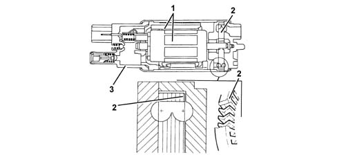
The fuel pump comprises a permanent-magnet electric motor (1) which controls the pump impeller (2), and a terminal-carrier cover (3), which contains the electrical and hydraulic connections.
The pump stage is the single type with peripheral flow, with high performance in low voltage and temperature conditions.
Its advantages compared with pumps operating in accordance with the positive-displacement principle are:
- light weight
- small in size.
INERTIA SWITCH
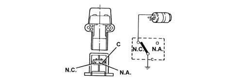
The inertia switch is fitted on the diver's side near the bolt fixing the running board to the front door pillar. In the case of an impact to the vehicle, it interrupts the connection to earth for the electric fuel pump and consequently the supply of fuel to the injection system.
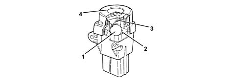
A steel ball (1) mounted in a conical housing (2) is normally locked by the attraction force of an adjacent magnet.
For specific acceleration loads, the ball is released from the magnetic clip and gradually comes out of the conical housing in an upwards movement following the angle of the cone.
Above the ball, there is a quick-trip mechanism (3) which forms the normally closed (N.C.) electric circuit.
When the mechanism is struck by the ball, it changes position from an N.C. circuit to a normally open (N.A.) circuit, breaking the fuel pump's earth circuit.
The switch can be reset by pressing a button protected by a soft cover (4).
Even after an apparently minor impact, if there is a smell of fuel or leaks are noticed from the fuel system, do not turn the switch back on, but search for the cause of the problem and remedy it to prevent the risk of fire. Otherwise, if no leaks are noted and the car is able to drive off, press the button to reactivate the pump.
COMPONENT DESCRIPTION
SUBMERGED PUMP ASSEMBLY COMPLETE WITH FUEL GAUGE SENDER UNIT
The fuel pump forms a single assembly with the fuel gauge sender unit and fuel filter; the components cannot be replaced individually.
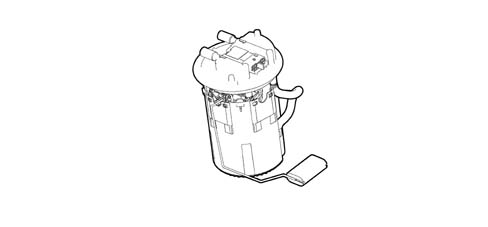
Electric fuel pump
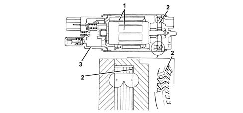
The fuel pump comprises a permanent-magnet electric motor (1) which controls the pump impeller (2), and a terminal-carrier cover (3), which contains the electrical and hydraulic connections.
The pump stage is of the single type with peripheral flow, with high performance under low voltage and temperature conditions.
Its advantages compared with pumps operating in accordance with the positive-displacement principle are:
- light weight
- small in size.
INERTIA SWITCH
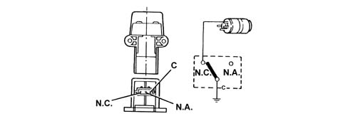
The inertia switch is fitted on the diver's side near the bolt fixing the running board to the front door pillar. In the case of an impact to the vehicle, it interrupts the connection to earth for the electric fuel pump and consequently the supply of fuel to the injection system.
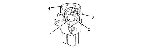
A steel ball (1) mounted in a conical housing (2) is normally locked by the attraction force of an adjacent magnet.
For specific acceleration loads, the ball is released from the magnetic clip and gradually comes out of the conical housing in an upwards movement following the angle of the cone.
Above the ball, there is a quick-trip mechanism (3) which forms the normally closed (N.C.) electric circuit.
When the mechanism is struck by the ball, it changes position from an N.C. circuit to a normally open (N.O.) circuit, breaking the fuel pump's earth circuit.
The switch can be reset by pressing a button protected by a soft cover (4).
After a crash, even if minor, if a smell of combustion or fuel leaks are perceived, do not reset the switch, but seek the cause of the fault and eliminate it, in order to avoid risks of fire. Otherwise, if there are no leaks and the vehicle can be restarted, press the button to reactivate the pump.
Parts & tools for this job For 2000 Alfa Romeo 147
- PARTEngine gasket setSearch: Alfa Romeo 147 2000 engine gasket set
- TOOLTorque wrenchSearch: 3/8 inch torque wrench
- TOOLFeeler gauge setSearch: feeler gauge set
Links open Amazon search results in a new tab. As an Amazon Associate I earn from qualifying purchases.