
Busbars
- Make
- Aston Martin
- Model
- DB9 Factory Workshop Manual
- Year
- Issue 2, 2005
- Section
- Wiring and Circuit Protection › Busbars
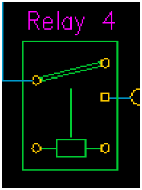
Another significant component in the circuits is a relay, this is in simple terms a switch that operates on the principal of electromagnetism. Below is the circuit symbol for a typical relay. The relay shown below is a normally open relay in its inoperative state i.e The arm is in the open position.
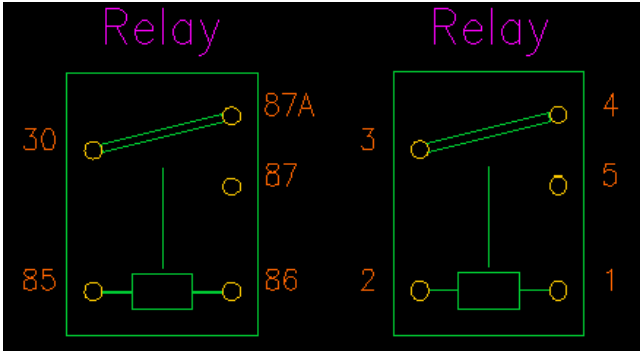
Relays can have either 4 or 5 terminals on the base. The circuit of the relay is shown on the base or the side of the housing. There are 2 types of numbering convention for the relay terminals, both of which are shown below.
Below is a circuit diagram to show the function and operation of a relay in a simple circuit.
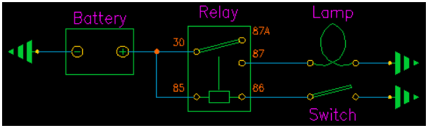
The current from a battery for example flows through the wires to the high power normally open switch (The arm between pins 30 & 87A) and the low power coil (The box between pins 85 & 86). As you can see in the example above the lamp is in not illuminated, because the switch is open.
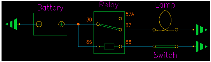
For the relay to operate there needs to be current flow through the low power coil i.e Current in to the coil then through to an earth. The current passes through the relay coil and creates a magnetic field, this magnetic field is strong enough to ‘grab’ the high power normally open switch.
The magnetic field pulls the switch from it’s normally open contact to a normally closed contact. The normally closed contact has a path to an earth, in this case it goes through a lamp.
The high power current then flows through the high power normally open switch through the lamp and then to an earth. This can be seen more clearly in the diagram below.Lamp Illuminates
Busbars
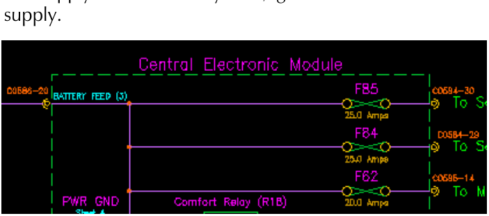
A busbar is where a electrical supply is fed into a conductive bar, wire or pcb track and various modules or components ‘tap’ into this busbar to draw their required power. The Central Electronic Module has 4 of these busbars internally, each of which is supplied from an external power supply, that supply can be a battery feed, ignition feed or a switched supply.
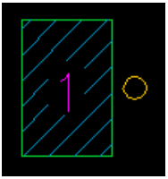
The symbol shown below is the symbol used on the circuits for a busbar, the number inside the box refers to the busbar number in the Central Electronic Module.
Fuses
A fuse is a device used to protect a module or component from excessive electrical current which can cause damage or destroy that module or component. In practice the fuse is placed in between the power source and the module or component that is being protected.
The size or ‘Rating’ of the fuse in amps is calculated according to the power requirements of the module or component it is protecting with other factors being taken into consideration. If the rating has been calculated correctly then the fuse will ‘blow’ when excessive current passes through it before any harm or permanent damage occurs to the module or component it is protecting.
Parts & tools for this job For 2005 Aston Martin DB9
- TOOLDigital multimeterSearch: automotive digital multimeter
- PARTAssorted fuse kitSearch: car fuse assortment kit
- TOOLWire crimper and connector kitSearch: wire crimper connector kit
Links open Amazon search results in a new tab. As an Amazon Associate I earn from qualifying purchases.