
Twisted Wires
- Make
- Aston Martin
- Model
- DB9 Factory Workshop Manual
- Year
- Issue 2, 2005
- Section
- Wiring and Circuit Protection › Twisted Wires
Twisted Wires
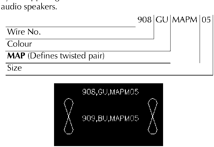
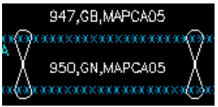
The ‘figure of 8’ shown on circuits as below denotes a twisted wire and shows the wires that are twisted together. A wire generates a certain amount of ‘electrical noise’ when a current is passed through it. By twisting the 2 wires together the ‘electrical noise’ is cancelled out on each wire by the opposing wire. This is used more on sensors and audio speakers.
Screened and Twisted Screen Wires
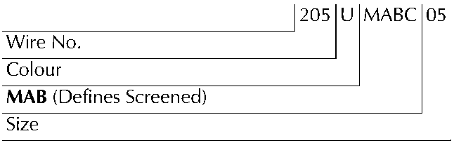
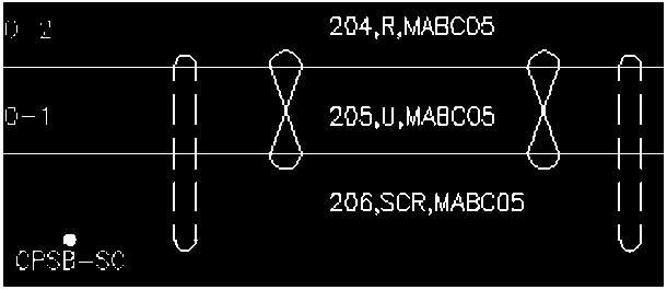
The signals through a wire can be affected by externally generated electrical noise. To reduce the external interference the wires are placed inside a conductive sleeve. One end of the conductive sleeve is always open whilst the other end can be terminated to a ground, to a component, or left open.
The symbol for the screen is an oval with the wires that are to be screened inside it. The letters ‘SCR’ define the screen.
Controller Area Network (CAN)
Controller Area Network (CAN) is the wiring between intelligent modules of the vehicle. This wiring carries the electronic data around the vehicle allowing the various modules and components to interrogate the network and read their specific data signals.
There are 2 different speeds of network.
Low speed - Transmits at 125,000 bits per second. Mainly for body controller systems such as seats and doors
High speed - Transmits at 500,000 bits per second. Mainly for engine management and powertrain associated systems such as ABS.
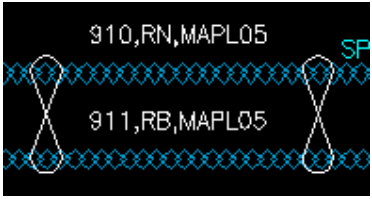
All wiring in the CAN is twisted. The twisted wires always consist of one wire with a black trace in it for the negative side and one with a brown trace in it for the positive.
High Speed CAN wire
Low Speed CAN wire
The symbol below shows a module or a component connector with the pin numbers that have CAN wires coming from them.
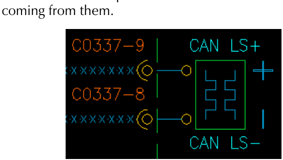
‘CAN LS+’ - Low speed CAN positive side
‘CAN LS-’ - Low speed CAN Negative Side
This naming convention also applies to the High Speed CAN network.
To aid identification of the different speed CAN’s in the vehicle different colours of wire have been used, e.g. the Low Speed Volcano is GB twisted with GN, the High Speed Volcano is RB twisted with RN.
There is attached on a separate page a list for wire colour abbreviations and what colour they refer to.
Parts & tools for this job For 2005 Aston Martin DB9
- TOOLDigital multimeterSearch: automotive digital multimeter
- PARTAssorted fuse kitSearch: car fuse assortment kit
- TOOLWire crimper and connector kitSearch: wire crimper connector kit
Links open Amazon search results in a new tab. As an Amazon Associate I earn from qualifying purchases.