
Splices
- Make
- Aston Martin
- Model
- DB9 Factory Workshop Manual
- Year
- Issue 2, 2005
- Section
- Wiring and Circuit Protection › Splices
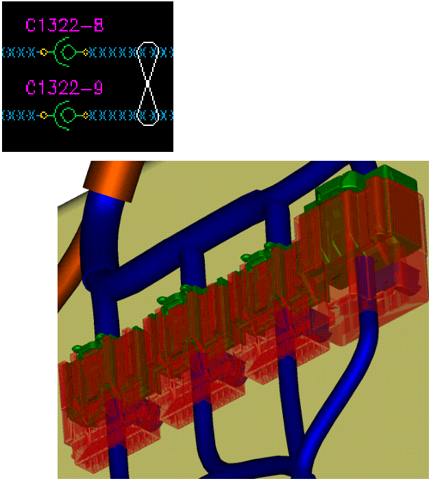
The terminals in a connector housing can have a special coating on them. This coating if required is selected using the following criteria.
- A specific coating requested by component / system owner.
Or
- The current passing through the terminal.
- The environment the connector is to be situated with respect to temperature.
- The open circuit voltage passing through the terminal at a given.
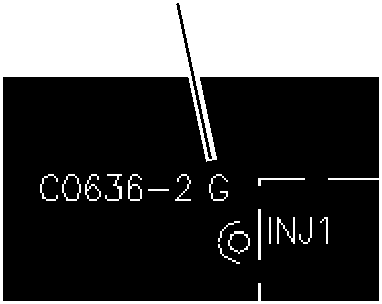
Depending on the above criteria the coating, if required, can either be gold, silver, phosphor bronze. Generally tin is the common plating on the terminals but there are some that are gold. These are identified in the circuits with the letter ‘G’ which stands for gold after the connector number. An example of this is shown below.
| Gold plated pin | G |
Splices
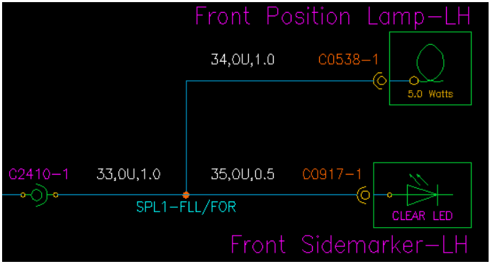
A splice is used where more than 2 wires that have the same requirement i.e. they need the same signal and meet in the same harness. In the example below the Front Position Lamp-LH and Front Side marker-LH require the same output signal from the CEM. Therefore the 2 wires for the lamps are spliced into the output wire from the CEM on the Forward Harness.
| SPL1 | FLL | FOR | |
| Splice No. | |||
| Associated name | |||
| Harness that the splice is on |
Tracing Spliced Wires
Some splices appear on pages as a wire that goes to one spot and seems to terminate in space. An example of this is shown below.
Splice Origin Page
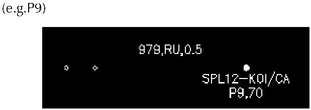
Other Page(s) on which the splice occurs.
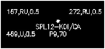
A separate page is attached containing a list of splice abbreviations and the harness to which they refer.
Parts & tools for this job For 2005 Aston Martin DB9
- TOOLDigital multimeterSearch: automotive digital multimeter
- PARTAssorted fuse kitSearch: car fuse assortment kit
- TOOLWire crimper and connector kitSearch: wire crimper connector kit
Links open Amazon search results in a new tab. As an Amazon Associate I earn from qualifying purchases.