
Tpms control unit operation check
- Make
- Fiat
- Model
- Bravo Factory Service Manual
- Year
- 2007–2014
- Section
- Hubs and wheels › Tpms control unit operation check
TPMS CONTROL UNIT OPERATION CHECK
| STEP | CHECK TO BE PERFORMED | REMEDIAL ACTION IF THE CHECK IS NOT OK |
|---|---|---|
| 1 | Control unit +30 power supply check Select the VOLTMETER mode from the INSTRUMENT menu Connect pin 1 to earth of the CPP control unit See E7060 TYRE INFLATION PRESSURE CONTROL SYSTEM Check that there is a battery voltage of 12 V Move on to Step 2 | Restore the correct continuity for the wiring. |
| 2 | Control unit +15 power supply check Position the diagnostic equipment. Select the VOLTMETER mode from the INSTRUMENT menu Turn the key to the MAR position Connect pin 16 to earth Check that there is a battery voltage of 12 V | Restore wiring continuity |
| 3 | Earth check Disconnect the negative battery terminal Disconnect the CPP control unit connector With the diagnostic instrument in ohmmeter mode Connect pin 10 of the wiring-side connector to earth Check that the resistance is less than 1 Ohm | Restore the right-hand side dashboard area earth. |
| 4 | A-bus serial line check Disconnect the negative battery terminal Disconnect the CPP control unit connector Disconnect the Body Computer-side connector With the diagnostic instrument in ohmmeter mode Connect pin 18 of the CPP-side connector to pin 10 of the Body Computer-side connector Check that the resistance is less than 1 Ohm | Restore the correct connection continuity. |
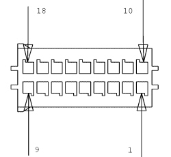
CPP control unit connector
| Pin | Function |
|---|---|
| 1 | Power supply +30 |
| 2 | L.F. transmitter power supply |
| 3 | Left rear L.F. transmitter signal |
| 4 | Left front L.F. transmitter signal |
| 5 | Right rear L.F. transmitter signal |
| 6 | Right front L.F. transmitter signal |
| 7 | N.C. |
| 8 | B-CAN H network |
| 9 | B-CAN L network |
| 10 | Earth |
| 11 | N.C. |
| 12 | Left-hand rear L.F. transmitter earth |
| 13 | Left-hand front L.F. transmitter earth |
| 14 | Right-hand rear L.F. transmitter earth |
| 15 | Right-hand front L.F. transmitter earth |
| 16 | Control unit ignition operated power supply (+15) |
| 17 | K line |
| 18 | A-bus serial line |
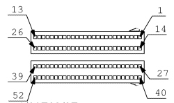
Body Computer-side connector
Parts & tools for this job For 2007 Fiat Bravo
- PARTWheel bearingSearch: Fiat Bravo 2007 wheel bearing
- TOOLBearing puller kitSearch: wheel bearing puller kit
- PARTCV boot kitSearch: Fiat Bravo 2007 cv boot kit
Links open Amazon search results in a new tab. As an Amazon Associate I earn from qualifying purchases.