
Timing diagrams
- Make
- Fiat
- Model
- Bravo /Brava (182) Factory Service Manual
- Year
- 1995–2001
- Section
- Engine › Timing diagrams
00 Introduction and technical dataTiming diagrams
| DESCRIPTION | 1929 D | 1910 TD | |
|---|---|---|---|
| Values in mm | |||
| 21a-21b Camshaft supports |
Ø1 | 23,990 ÷ 24,015 | - |
| Ø2 | 29,990 ÷ 30,015 | - | |
| 17-21a 17-21b Camshaft Supports | 0,030 ÷ 0,070 | - | |
| 32-12 Variation between ante-chamber plane and cylinder head plane |
- 0,765 ÷ 0,055 | - 0,150 ÷ -0,3 | |
TIMING DIAGRAMS
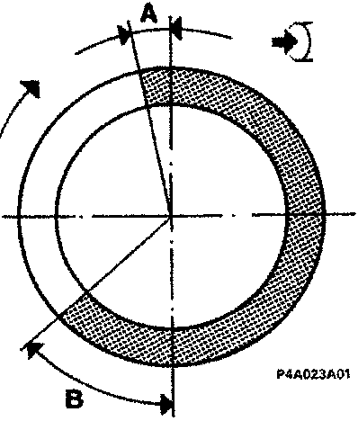
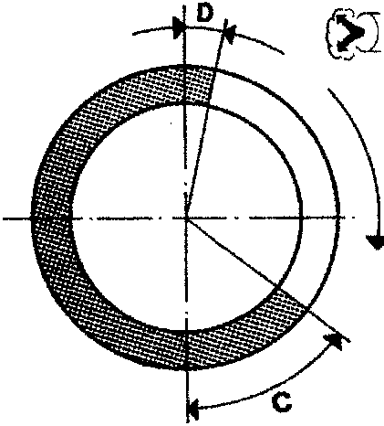
Timing angles
| A Inlet |
opens before TDC | 10° | N.D. | |
| B | closes after BDC | 42° | N.D. | |
| C Exhaust |
opens before BDC | 50° | N.D. | |
| D | closes after TDC | 2° | N.D. |
Original page
Parts & tools for this job For 1995 Fiat Bravo
- PARTEngine gasket setSearch: Fiat Bravo 1995 engine gasket set
- TOOLTorque wrenchSearch: 3/8 inch torque wrench
- TOOLFeeler gauge setSearch: feeler gauge set
Links open Amazon search results in a new tab. As an Amazon Associate I earn from qualifying purchases.