
Fuel system
- Make
- Fiat
- Model
- Bravo /Brava (182) Factory Service Manual
- Year
- 1995–2001
- Section
- Engine › Fuel system
00 Introduction and technical dataFuel system · page 1 of 3
COOLING SYSTEM
| Cooling circuit | coolant circulation via centrifugal pump, radiator and two speed electrical fan operated by two speed thermostatic switch | ||||
|---|---|---|---|---|---|
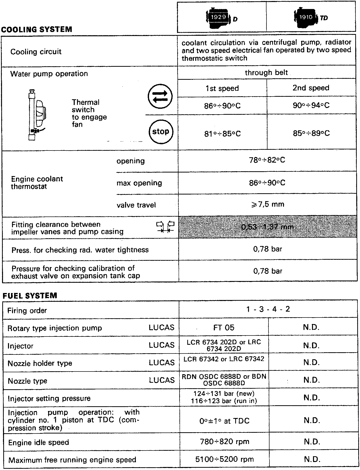
Thermal switch to engage fan |
Water pump operation | through belt | |||
| 1st speed | 2nd speed | ||||
| 86°÷90°C | 90°÷94°C | ||||
| 81°÷85°C | 85°÷89°C | ||||
| Engine coolant thermostat |
opening | 78°÷82°C | |||
| max opening | 86°÷90°C | ||||
| valve travel | ≥7,5 mm | ||||
| Fitting clearance between impeller vanes and pump casing | 0.53÷1.37 mm | ||||
| Press. for checking rad. water tightness | 0,78 bar | ||||
| Pressure for checking calibration of exhaust valve on expansion tank cap | 0,78 bar | ||||
FUEL SYSTEM
| Firing order | 1 - 3 - 4 - 2 | ||
|---|---|---|---|
| Rotary type injection pump | LUCAS | FT 05 | N.D. |
| Injector | LUCAS | LCR 6734 202D or LRC 6734 202D | N.D. |
| Nozzle holder type | LUCAS | LCR 67342 or LRC 67342 | N.D. |
| Nozzle type | LUCAS | RDN OSDC 6888D or BDN OSDC 6888D | N.D. |
| Injector setting pressure | 124÷131 bar (new) 116÷123 bar (run in) |
N.D. | |
| Injection pump operation: with cylinder no. 1 piston at TDC (compression stroke) | 0°±1° at TDC | N.D. | |
| Engine idle speed | 780÷820 rpm | N.D. | |
| Maximum free running engine speed | 5100÷5200 rpm | N.D. | |
Parts & tools for this job For 1995 Fiat Bravo
- PARTFuel filterSearch: Fiat Bravo 1995 fuel filter
- TOOLFuel pressure test kitSearch: fuel pressure test kit
- TOOLFuel line disconnect toolSearch: fuel line disconnect tool
Links open Amazon search results in a new tab. As an Amazon Associate I earn from qualifying purchases.