
Key to wiring diagram
- Make
- Fiat
- Model
- Bravo /Brava (182) Factory Service Manual
- Year
- 1995–2001
- Section
- Fuel system (1910 TD) › Key to wiring diagram
10 EngineKey to wiring diagram
Key to wiring diagram
| 1. Heater plugs warning light | 11. Injection system failure warning light |
| 2. Rev counter signal | 12. Debimeter |
| 3. Air conditioner relay | 13. Preheating control unit |
| 4. Air conditioner activation button | 14. System relay |
| 5. Fiat/Lancia Tester fault diagnosis point | 15. Borg Warner solenoid (E.G.R) |
| 6. Injector with controls | 16. Battery |
| 7. Rpm and TDC sensor | 17. Ignition switch |
| 8. Coolant temperature sensor | 18. Fast idle valve |
| 9. Accelerator lever position sensor | 19. Solenoid for advance adjustment device |
| 10. Intake air temperature sensor |
Rpm and phonic wheel sensor
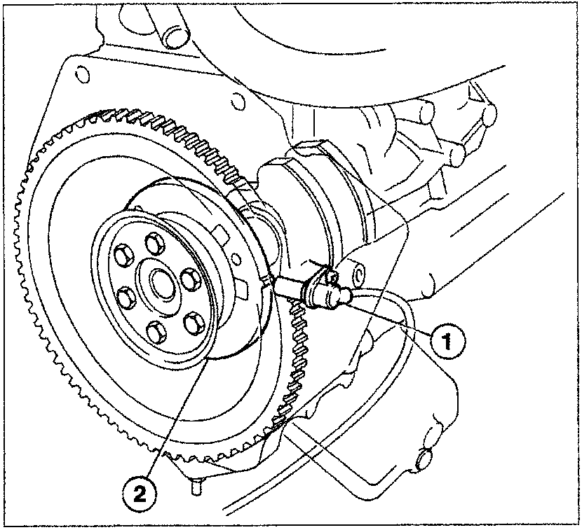
Specifications:
Gap
0.8 - 1.5 mm
Winding resistance
860 ohm ± 10% at 20°C
- Rpm sensor
- Phonic wheel
The rpm sensor is fitted on the crankcase and faces a phonic wheel located inside the crankcase and fastened to the crankshaft.
The steel phonic wheel is fitted with two reference dowels on the outer part of the circumferenc, each one located 10° after top dead centre.
When these dowels or teeth pass beneath the sensor, the gap brings about a change in the magnetic flux which in turn induces a current in the sensor coil windings.
This signal provides the control unit with information on engine rpm.
Parts & tools for this job For 1995 Fiat Bravo
- TOOLDigital multimeterSearch: automotive digital multimeter
- PARTAssorted fuse kitSearch: car fuse assortment kit
- TOOLWire crimper and connector kitSearch: wire crimper connector kit
Links open Amazon search results in a new tab. As an Amazon Associate I earn from qualifying purchases.