
Blow-by gas recirculation diagram)
- Make
- Fiat
- Model
- Bravo /Brava (182) Factory Service Manual
- Year
- 1995–2001
- Section
- Fuel system (1910 TD) › Blow-by gas recirculation diagram)
10 EngineBlow-by gas recirculation diagram) · page 1 of 2
BLOW-BY GAS RECIRCULATION DIAGRAM)
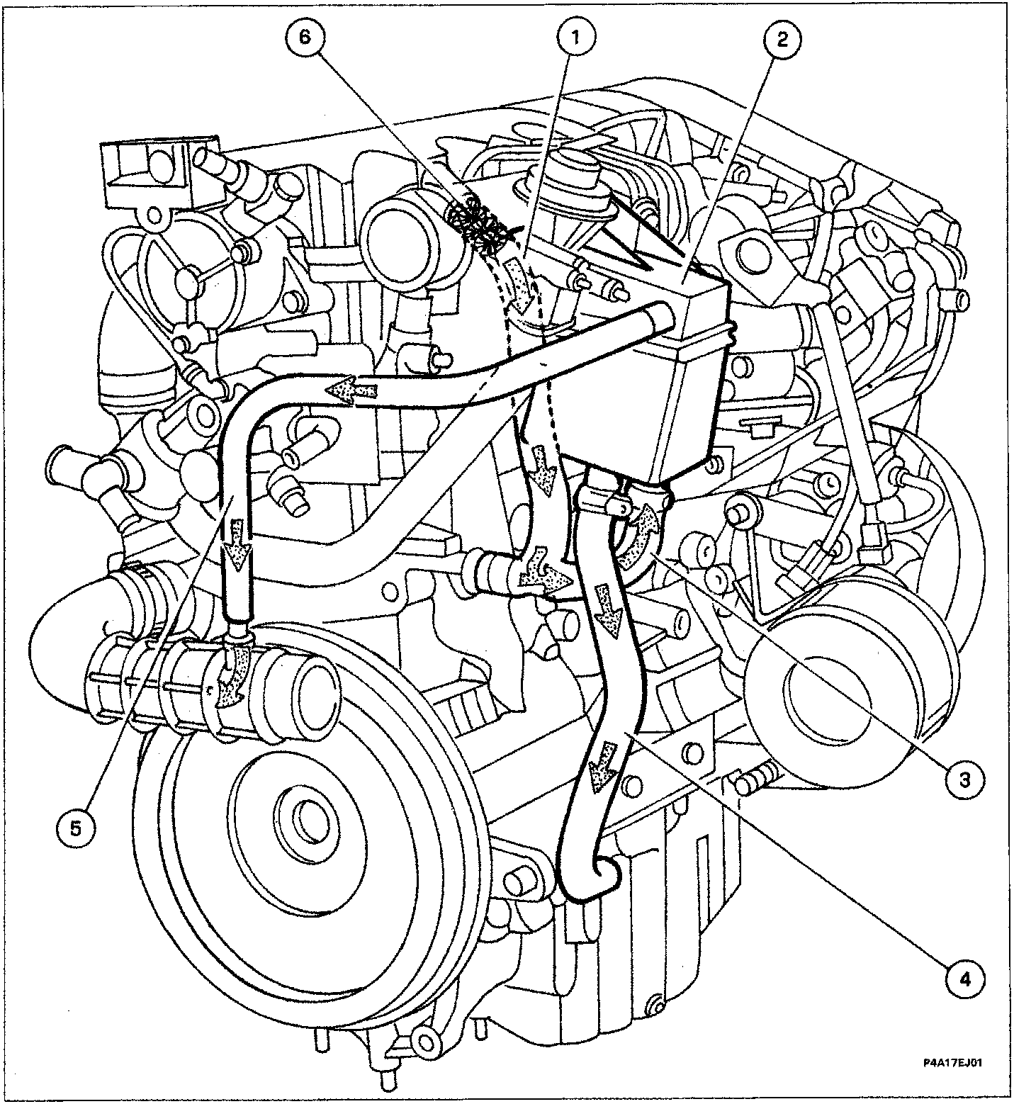
Crankcase emissions are made up of a mixture of air, diesel and burnt gases which leak through the piston rings, in addition to lubrication oil vapour.
This mixture is defined "blow-by" or "vent" gas.
Vent gases from the crankcase and cylinder head flow through pipe (3) to separator (2) where they lose part of their oil content in the vortex. This falls back to the sump through pipe (4) in the form of droplets (4).
The remaining gases flow through pipe (5) and are directed to the intake circuit.
Cylinder head gas outlet pipe (1) contains a flap trap (6) to prevent the pipe catching fire due to flame flash-back.
Parts & tools for this job For 1995 Fiat Bravo
- PARTFuel filterSearch: Fiat Bravo 1995 fuel filter
- TOOLFuel pressure test kitSearch: fuel pressure test kit
- TOOLFuel line disconnect toolSearch: fuel line disconnect tool
Links open Amazon search results in a new tab. As an Amazon Associate I earn from qualifying purchases.