
Operating description
- Make
- Fiat
- Model
- Bravo /Brava (182) Factory Service Manual
- Year
- 1995–2001
- Section
- Fuel system (1910 TD) › Operating description
The air flow meter (Debimeter) is hot film type. In this system, a heated membrane is placed in a measurement channel through which air is taken into the engine.
The film membrane is maintained at a constant temperature (~ 120°C above air temperature) by an adjacent heating coil.
The mass of air flowing through the measurement channel tends to remove heat from the membrane. To keep the membrane at constant temperature, a certain current must therefore flow through the heating coil. This current is measured by means of a Wheatstone bridge.
The measured current is therefore proportional to the flowing air mass.
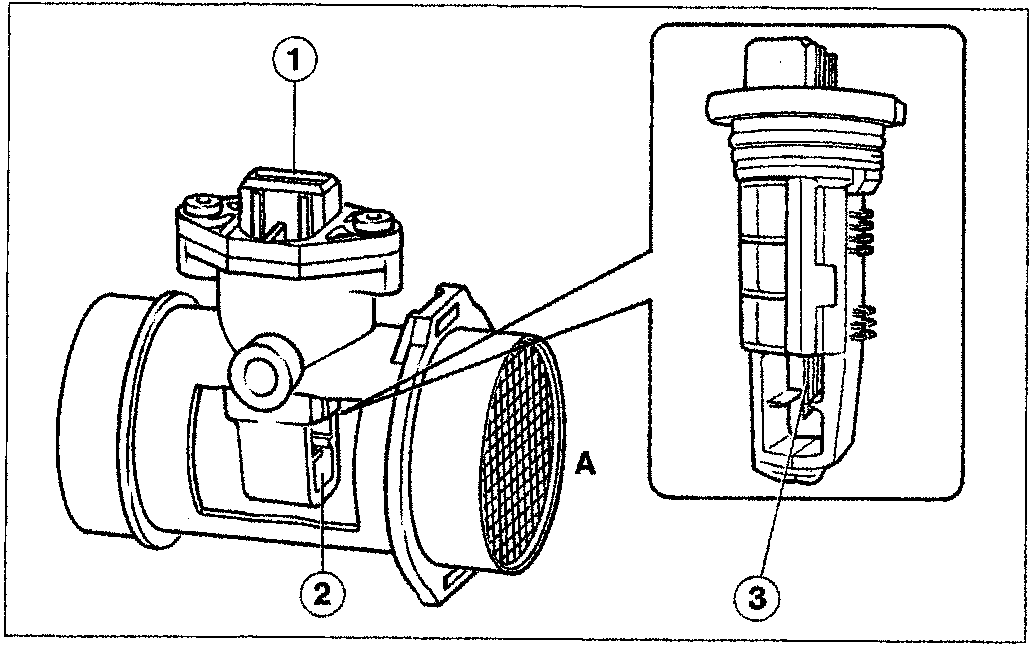
- Connector
- Measuring channel
- Hot film sensor
- A= Air intake
NOTE This debimeter measures air mass directly (not volume) and thus eliminates problems of temperature, altitude, pressure etc.
Operating description
The Wheatstone bridge (R3, R2, Rs, Rt+R1 format) is in equilibrium when Rs is about 120°C more than air temperature.
The air flowing through the membrane removes heat from Rs, and the bridge becomes imbalanced. This situation is deteced by the circuit connected to IC1, which controls transistor T1 to an extent proportional to bridge imbalance. T1 then sends more current through Rh to heat Rs and thus restore the bridge to equilibrium.
Circuit IC2 measures the current flowing through Rh. This current maintains the bridge in equilibrium and is thus proportional to the mass of air flowing through the air meter.
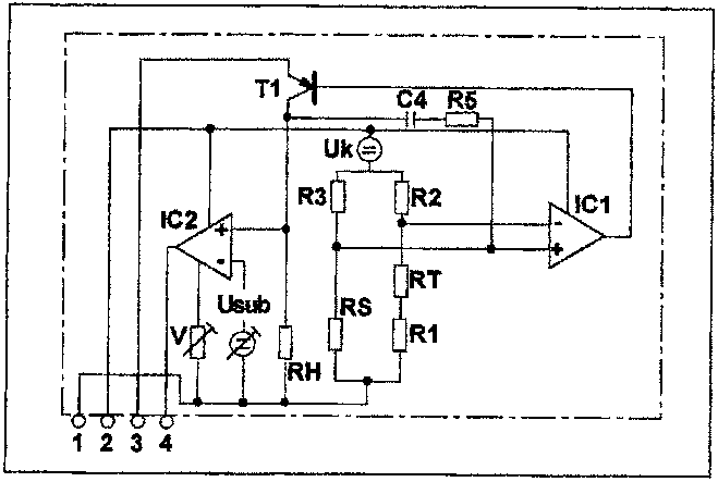
Wiring diagram of air flow meter
Parts & tools for this job For 1995 Fiat Bravo
- PARTFuel filterSearch: Fiat Bravo 1995 fuel filter
- TOOLFuel pressure test kitSearch: fuel pressure test kit
- TOOLFuel line disconnect toolSearch: fuel line disconnect tool
Links open Amazon search results in a new tab. As an Amazon Associate I earn from qualifying purchases.