
Fuel feed circuit
- Make
- Fiat
- Model
- Bravo /Brava (182) Factory Service Manual
- Year
- 1995–2001
- Section
- Fuel system (1910 TD) › Fuel feed circuit
FUEL FEED CIRCUIT
The main components of the fuel system are as follows: tank, filter, injection pump and injectors. Fuel flows from tank (6) to injection pump (2) through filter (7). A pump (9) is fitted upstream from filter (7) to prime the fuel if necessary (e.g., after replacing the fuel filter).
Rotary injection pump (2) ensures injectors (1) are properly supplied with fuel in the firing order 1-3-4-2.
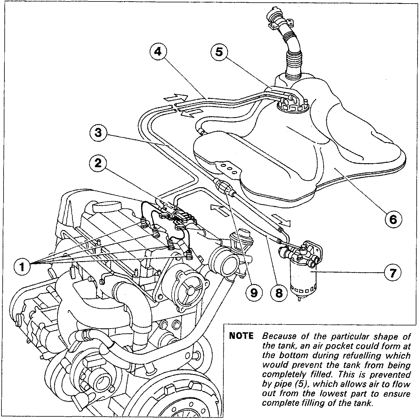
NOTE Because of the particular shape of the tank, an air pocket could form at the bottom during refuelling which would prevent the tank from being completely filled. This is prevented by pipe (5), which allows air to flow out from the lowest part to ensure complete filling of the tank.
- Injectors
- Injection pump
- Delivery line from tank to filter
- Return line (recirculation)
- Vent pipe
- Reservoir
- Fuel filter
- Fuel outlet line from filter to injection pump
- Hand-operated priming pump
Parts & tools for this job For 1995 Fiat Bravo
- TOOLDigital multimeterSearch: automotive digital multimeter
- PARTAssorted fuse kitSearch: car fuse assortment kit
- TOOLWire crimper and connector kitSearch: wire crimper connector kit
Links open Amazon search results in a new tab. As an Amazon Associate I earn from qualifying purchases.