
Fuel system components (page 3 of 3)
- Make
- Fiat
- Model
- Bravo /Brava (182) Factory Service Manual
- Year
- 1995–2001
- Section
- Fuel system (1910 TD)
10 EngineFuel system components · page 3 of 3
The air intake circuit is turbocharged by means of a Garrett GT15 turbocharger with waste-gate.
Air is taken in through intake (1) and flows through filter (5) before compression in exhaust gas-driven turbocharger (2). Air then flows through the heat exchanger (intercooler) (3).
The air assumes optimal temperature and density properties and then flows to the intake manifold (7) for distribution to the cylinders.
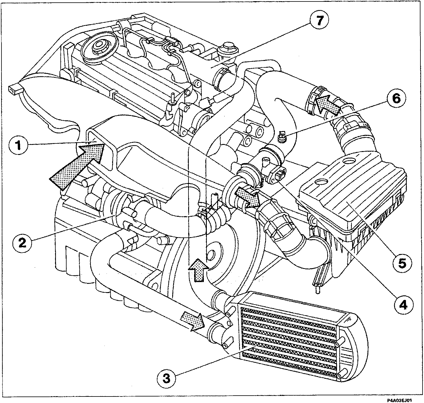
- Inlet fitting
- Turbocharger
- Heat exchanger (intercooler)
- Air flow meter (debimeter)
- Air cleaner
- Air temperature sensor
- Inlet manifold
Parts & tools for this job For 1995 Fiat Bravo
- PARTFuel filterSearch: Fiat Bravo 1995 fuel filter
- TOOLFuel pressure test kitSearch: fuel pressure test kit
- TOOLFuel line disconnect toolSearch: fuel line disconnect tool
Links open Amazon search results in a new tab. As an Amazon Associate I earn from qualifying purchases.