
Blow-by gas recirculation diagram) (page 2 of 2)
- Make
- Fiat
- Model
- Bravo /Brava (182) Factory Service Manual
- Year
- 1995–2001
- Section
- Fuel system (1910 TD)
This system directs a proportion of the exhaust gases to the intake under certain engine operating conditions.
The process dilutes the fuel mixture with inert gases to lower the temperature peak in the combustion chamber. This reduces the formation of nitrogen oxides to bring about a 30-50 % reduction in emissions. Exhaust gas recirculation is allowed only at medium-low loads, when the air - fuel ratio is very high and engine operation is not impaired by the presence of inert gases instead of air.
The recirculation system is controlled by electronic control unit (1), which receives input signals from a potentiometer on the accelerator lever (on the injection pump) and from the rpm and coolant temperature sensors. It produces an output signal which controls the Borg Warner modulator solenoid and hence the E.G.R. (2).
The E.G.R. is connected to the atmosphere through filter (3). According to an input signal, the valve directs a higher or lower vacuum from the brake servo vacuum pump (4) to the Pierburg EGR valve (5). If the vacuum is sufficient, this valve opens to bring the exhaust manifold into communication with the intake manifold.
The amount of gas recirculated can therefore be altered by adjusting Pierburg E.G.R. valve opening continuously on the basis of maps saved in the ECU memory and the degree of opening, which is in turn dependent on signals received.
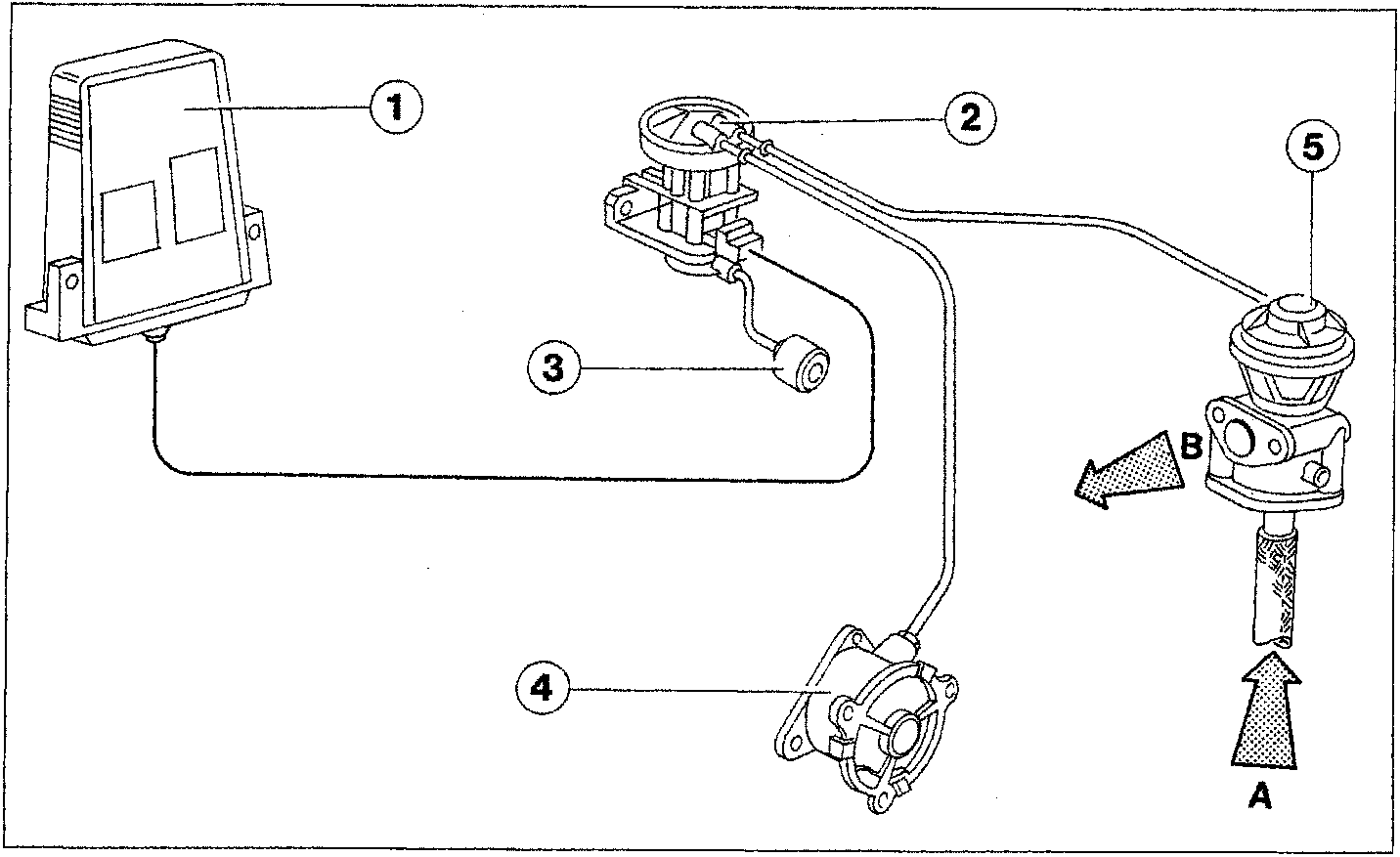
- Electronic control unit
- Borg Warner modulator solenoid controlling EGR.
- Atmospheric intake filter
- Vacuum pump for brake servo
- E.G.R. valve.
- A. Gas from the exhaust manifold
- B. Gas sent to intake
Parts & tools for this job For 1995 Fiat Bravo
- PARTFuel filterSearch: Fiat Bravo 1995 fuel filter
- TOOLFuel pressure test kitSearch: fuel pressure test kit
- TOOLFuel line disconnect toolSearch: fuel line disconnect tool
Links open Amazon search results in a new tab. As an Amazon Associate I earn from qualifying purchases.