
Workshop Manuals Factory service & repair Fiat
01 00 Introduction and technical data02 10 Engine03 18 Clutch04 21 Gearbox and differential05 33 Braking system06 41 Steering07 44 Suspension and wheels08 50 Auxiliary units09 55 Electrical system10 70 Bodywork
Fiat Bravo/Brava (182) Factory Service Manual (1995-2001)02 · 10 Engine
02 · Engine

Heater plugs control unit

Make
Fiat
Model
Bravo /Brava (182) Factory Service Manual
Year
1995–2001
Section
Fuel system (98 range, 1910 JTD) › Heater plugs control unit
10 EngineHeater plugs control unit

HEATER PLUGS CONTROL UNIT
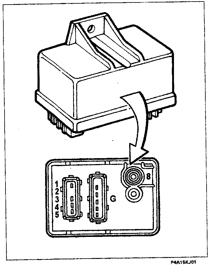
Diagram of the heater plugs control unit showing the main housing and the connector pin-out at the base with numbered pins 1 through 5, G, and 8.
The operation of the heater plugs takes place through the heater plugs control unit under the direct control of the injection control unit. There is an "intelligent" relay inside the heater plugs control unit which sends feed-back to the injection control unit which is thereby informed of any failure in the heater plugs control unit or a short circuit to earth of the heater plugs. The diagram illustrates the connectors at the base of the heater plugs control unit and the pin-out:
  1. Earth
  2. Connected to earth
  3. Injection control unit (pin 3-38)
  4. Injection control unit (pin 3-51)
  5. Injection control unit (pin 2-1)
  6. Battery positive (+30)
  7. G. Heater plugs (only 4 outlets are used)

ACCELERATOR PEDAL POTENTIOMETER
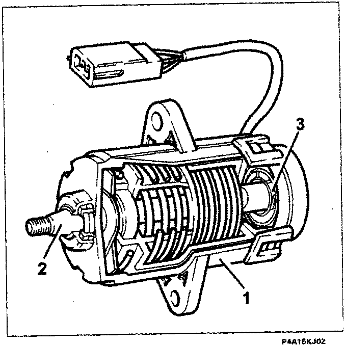
Cutaway diagram of the accelerator pedal potentiometer showing the casing (1), shaft (2), and internal potentiometers (3).
The position of the accelerator pedal is transformed into an electrical voltage signal and is sent to the injection control unit by the potentiometer connected to the pedal. The accelerator pedal position signal is processed together with the information relating to the speed to obtain the injection times and pressure. The sensor is made up of a casing (1) fixed to the pedals by a flange, which contains a shaft (2), in an axial position, connected to the two potentiometers (3): one main one and one safety one. There is a coil spring on the shaft which ensures the correct resistance to the pressure, whilst a second spring ensures the return on release.

Parts & tools for this job For 1995 Fiat Bravo

Links open Amazon search results in a new tab. As an Amazon Associate I earn from qualifying purchases.