
Pressure pump
- Make
- Fiat
- Model
- Bravo /Brava (182) Factory Service Manual
- Year
- 1995–2001
- Section
- Fuel system (98 range, 1910 JTD) › Pressure pump
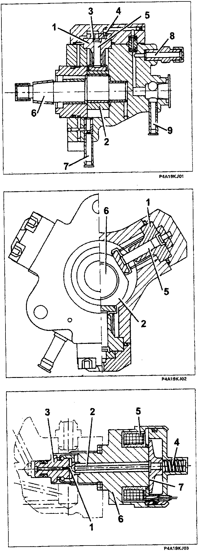
PRESSURE PUMP
The pressure pump is the radialjet type with three radial pistons (total capacity 0.657. cc) and is operated by the timing belt.
Each pumping unit consists of:
- a piston (5) operated by a cam (2) fixed to the pump (6) shaft;
- an inlet valve with a shim (3);
- a supply ball valve (4).
The pressure pump should receive a pressure of at least 0.5 bar; for this reason, the fuel system is equipped with an auxiliary electric pump immersed in the tank.
The pressure pump is lubricated and cooled by the same diesel fuel through ducts and is capable of supplying a maximum pressure of 1350 bar.
- Cylinder
- Cam
- Inlet valve
- Supply ball valve
- Piston
- Pump shaft
- Diesel inlet connector - low pressure - from fuel filter
- Diesel supply connector - high pressure - to manifold (rail)
- Diesel supply connector - low pressure - recirculation
FUEL PRESSURE REGULATOR
The fuel pressure sensor is fitted on the pressure pump and, operated directly by the injection control unit, regulates the supply pressure of the fuel to the injectors.
The pressure regulator basically consists of the following components:
- Shutter with ball
- Pin
- Valve
- Pre-loading spring
- Coil
- Casing
- Keeper
Parts & tools for this job For 1995 Fiat Bravo
- PARTFuel filterSearch: Fiat Bravo 1995 fuel filter
- TOOLFuel pressure test kitSearch: fuel pressure test kit
- TOOLFuel line disconnect toolSearch: fuel line disconnect tool
Links open Amazon search results in a new tab. As an Amazon Associate I earn from qualifying purchases.