
Inertia safety switch
- Make
- Fiat
- Model
- Bravo /Brava (182) Factory Service Manual
- Year
- 1995–2001
- Section
- Fuel system (98 range, 1910 JTD) › Inertia safety switch
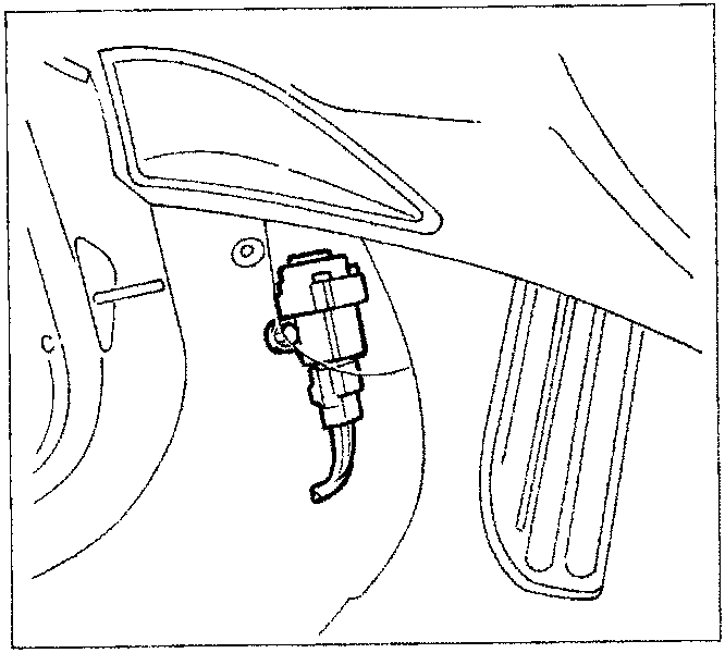
INERTIA SAFETY SWITCH
In order to increase the safety of the occupants, in the case of an impact, the vehicle is equipped with an inertia switch located inside the passenger compartment, fixed to the left of the side panel.
This sensor reduces the risk of fire (as a result of fuel escaping) by deactivating the auxiliary electric pump which supplies the injection circuit.
The inertia switch consists of a steel ball fitted in a (tapered) housing and kept in position by the attraction force of a permanent magnet.
If the vehicle is involved in a violent crash, the ball is released from the magnetic clip and opens the normally closed (N.C.) electrical circuit interrupting the connection to earth for the auxiliary electric pump and, as a result, the supply to the injection system.
To restore the connection to earth for the auxiliary electric pump, the seat must be moved backwards and the switch pressed until it is heard to click.
Even after an apparently minor impact, if there is a smell of fuel or there are leaks from the fuel system, do not turn the inertia switch back on, but search first for the cause of the problem and remedy it to avoid the risk of fire.
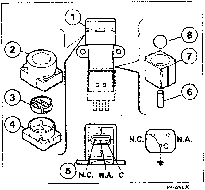
Inertia switch components
- Complete inertia sensor
- Outer casing
- Button
- Upper side
- Engagement side
- Permanent magnet
- Permanent magnet housing
- Steel ball
C Common terminal
N.C. Normally closed contact
N.A. Normally open contact
Parts & tools for this job For 1995 Fiat Bravo
- TOOLOBD2 scannerSearch: OBD2 scanner
- TOOLDigital multimeterSearch: automotive digital multimeter
- TOOLBack-probe test leadsSearch: back probe test leads
Links open Amazon search results in a new tab. As an Amazon Associate I earn from qualifying purchases.