
Air distribution (page 2 of 2)
- Make
- Fiat
- Model
- Bravo /Brava (182) Factory Service Manual
- Year
- 1995–2001
- Section
- Climate control (98 range)
50 Auxiliary unitsAir distribution · page 2 of 2
The climate control system consists of the following components:
- a variable flow rate compressor (SKROLL for 1242 16v and 1910 JTD versions - NIPPONDENSO TV 12SC for other versions) which is fixed to the engine by brackets;
- a condenser which is a heat exchanger fitted in front of the engine coolant radiator;
- a drier filter which is located near the left side of the condenser;
- an evaporator which is the second heat exchanger for the system and is located in the above mentioned assembly;
- an expansion valve which is fitted on the evaporator inlet duct;
- various rigid and flexible pipes which connect the various system components;
- a threee stage pressure switch which is fitted on the drier filter.
There are two small pipes, fitted to the high and low pressure pipes, with a needle valve which is designed to drain and repressurize the system.
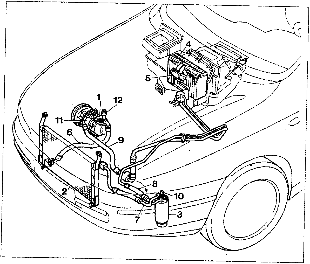
- Compressor
- Condenser
- Drier filter
- Evaporator
- Expansion valve
- Pipe between compressor and condenser
- Pipe between condenser and drier filter
- Pipe between filter and evaporator
- Pipe between evaporator and compressor
- Three stage pressure switch
- Needle valve for draining the system (low pressure side)
- Needle valve for draining and repressurizing the system (high pressure side)
Parts & tools for this job For 1995 Fiat Bravo
- TOOLA/C manifold gauge setSearch: AC manifold gauge set
- TOOLUV leak detection kitSearch: AC UV leak detection kit
- PARTCabin filterSearch: Fiat Bravo 1995 cabin filter
Links open Amazon search results in a new tab. As an Amazon Associate I earn from qualifying purchases.