
"MAX-DEF" Function (page 2 of 2)
- Make
- Fiat
- Model
- Bravo /Brava (182) Factory Service Manual
- Year
- 1995–2001
- Section
- Climate control (98 range)
Case A: the engine management control unit (1) receives the signal to engage the compressor (a) directly from the control switch (2): the same signal also arrives as a go ahead (b) after having passed through the climate control control unit (3) and the four stage pressure switch (4): if the pressure is in the refrigeration circuit is not correct, this signal is, in effect, interrupted. Lastly, if other particular exclusion conditions exist (e.g. maximum power request, idling, etc.), then the control unit (1) sends the command (c) to engage the compressor (6) via the relay (5).
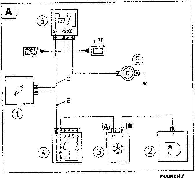
1242 - 1581 - 1998 - 1910 JTD Engines
- Injection control unit
- Climate control controls
- Climate control control unit
- Four stage pressure switch
- Compressor relay
- Compressor
Case B: the signal (a) to engage the compressor is sent, from the control switch (2), via the climate control control unit (3), the four stage pressure switch (4) and the thermal switch (7), to the compressor engagement relay (5). If the conditions for disengaging the compressor (6) exist, (for example maximum power request, idle speed, etc.), then a signal (b) is sent by the EGR control unit (1) to a remote control switch (8) and the compressor is switched off.
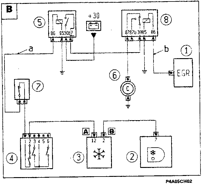
1910 TD 75 engine (Soft)
- EGR control unit
- Climate control controls
- Climate control control unit
- Four stage pressure switch
- Compressor relay
- Compressor
- Thermostatic switch on water pump
- Remote control switch for disengaging compressor
Parts & tools for this job For 1995 Fiat Bravo
- TOOLA/C manifold gauge setSearch: AC manifold gauge set
- TOOLUV leak detection kitSearch: AC UV leak detection kit
- PARTCabin filterSearch: Fiat Bravo 1995 cabin filter
Links open Amazon search results in a new tab. As an Amazon Associate I earn from qualifying purchases.