
Harrison v 5 variable displacement compressor
- Make
- Fiat
- Model
- Bravo /Brava (182) Factory Service Manual
- Year
- 1995–2001
- Section
- Compressor › Harrison v 5 variable displacement compressor
‹ Prev Location of heating/ventilation system components and variants for different engine versionsNext ›
50 Auxiliary unitsHarrison v 5 variable displacement compressor · page 1 of 2
HARRISON V 5 VARIABLE DISPLACEMENT COMPRESSOR
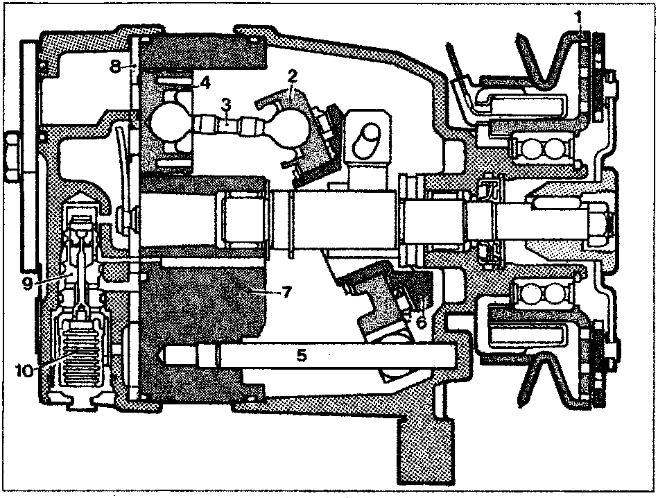
Cross section through V 5 compressor
- Pulley with electromagnetic coupling.
- Disc
- Connecting rod
- Piston
- Disc drive pin
- Tilted plane
- Engine block
- Plate with intake and outlet valves
- Regulation valve
- Control bellows for valve (9)
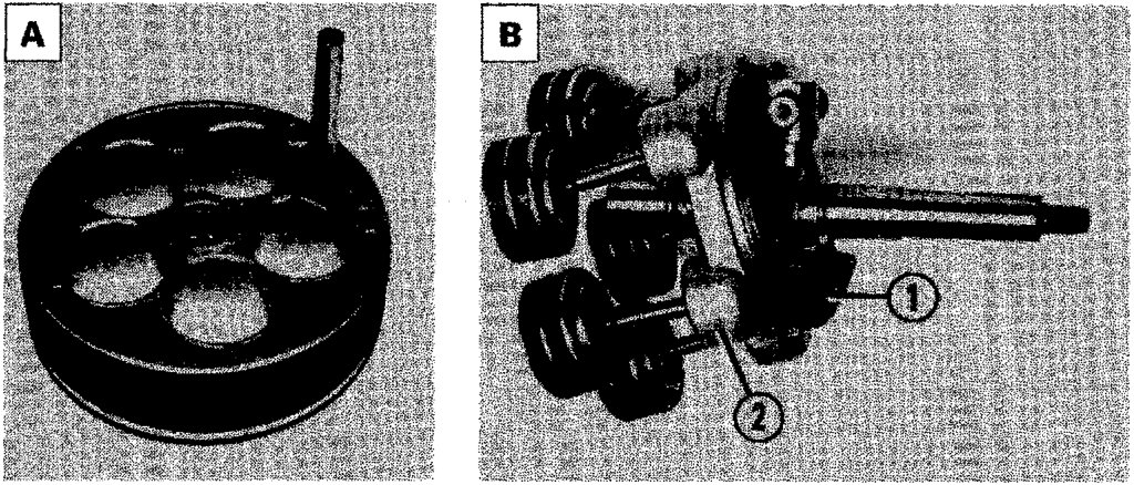
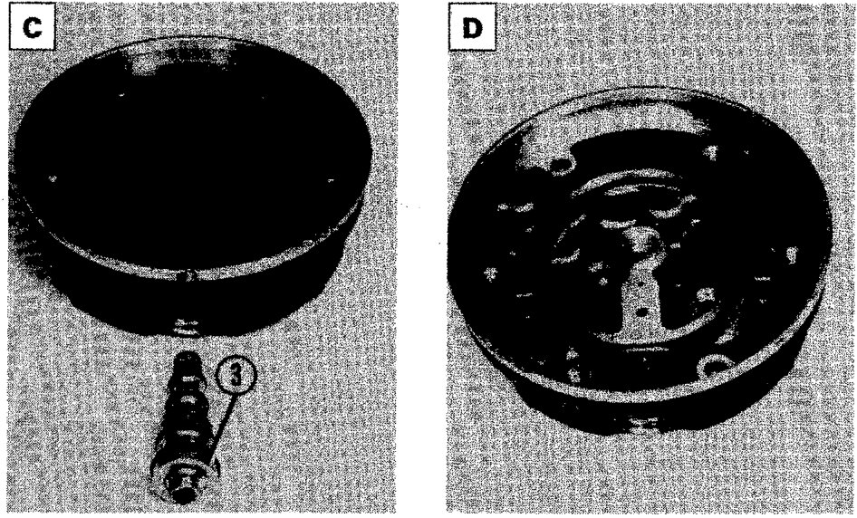
The compressor consists essentially of:
- a base (detail A) containing piston sleeves;
- a unit (detail B) consisting of a shaft fitted with a tilted plane (1). On this rests disc (2) mounted on rollers. This is connected by means of ball joints to five connecting rods connected in turn to pistons;
- a cylinder head (part D) containing inlet/outlet valves and seat for regulation valve (3);
- assembly (4) made up of gasket (5), plate (6) with inlet and outlet valves and intake diaphragm (7) is arranged on the head in a certain position (detail C).
‹ Prev Location of heating/ventilation system components and variants for different engine versionsNext ›
Parts & tools for this job For 1995 Fiat Bravo
- TOOLTorque wrenchSearch: 3/8 inch torque wrench
- TOOLSocket setSearch: socket set metric
- BOOKHaynes manualSearch: Haynes manual Fiat Bravo
Links open Amazon search results in a new tab. As an Amazon Associate I earn from qualifying purchases.