
Operation
- Make
- Fiat
- Model
- Bravo /Brava (182) Factory Service Manual
- Year
- 1995–2001
- Section
- Compressor › Operation
50 Auxiliary unitsOperation · page 1 of 2
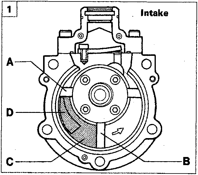
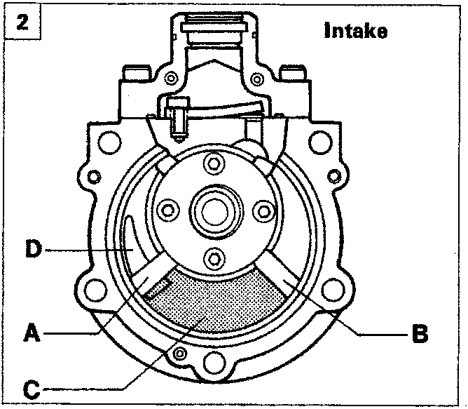
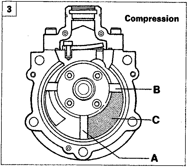
OPERATION
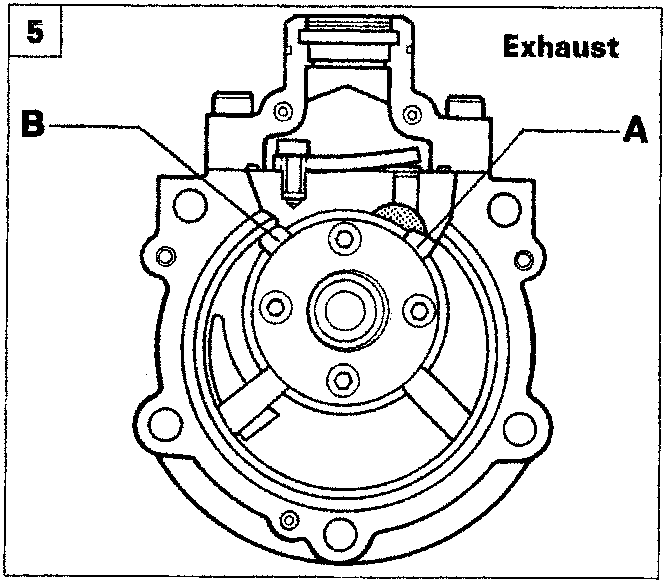
- Gas is taken in through slot (D) and then expands in compartment (C), which is delimited by vanes (A) and (B).
- The new position of vanes (A) and (B) ensures that compartment (C) is at maximum volume. In particular, vane (A) cuts off communication between compartment (C) and slot (D) to complete the intake stage.
- Compartment (C) reduces in volume and gas pressure increases: the compression stage thus begins.
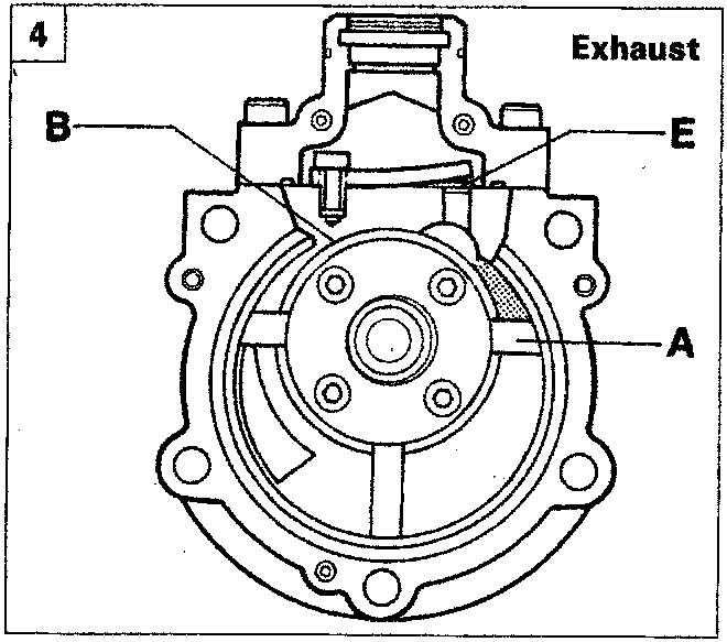
- Gas pressure increases further until strip valve (E) opens: at this moment the compression stage ends and the exhaust stage begins.
- When vanes (A) and (B) take up the position shown in the figure, the exhaust stage is complete.
Parts & tools for this job For 1995 Fiat Bravo
- TOOLTorque wrenchSearch: 3/8 inch torque wrench
- TOOLSocket setSearch: socket set metric
- BOOKHaynes manualSearch: Haynes manual Fiat Bravo
Links open Amazon search results in a new tab. As an Amazon Associate I earn from qualifying purchases.