
Nippodenso compressor
- Make
- Fiat
- Model
- Bravo /Brava (182) Factory Service Manual
- Year
- 1995–2001
- Section
- Compressor › Nippodenso compressor
NIPPODENSO COMPRESSOR
The Nippodenso compressor fitted to the petrol and 1910 TD versions is vane type and equipped with a pressure regulator that adjusts flow when evaporator temperature reaches values when freezing could occur. This situation is indicated by a drop in compressor intake pressure.
The compressor essentially consists of case (1), which contains chamber (2). Four vanes (3) turning inside the chamber are driven by hub (4), whose axis of rotation does not coincide with the theoretical chamber centre line. The geometrical configuration of the chamber ensures that the rotating vanes are always in contact with the inside surface of the chamber. The assembly thus allows the space between one vane and the next to be altered during rotation.
Two covers are secured to case (1), one at the front (5) and one at the rear (6). These contain an inlet or low pressure chamber (7) and a high pressure chamber (8). Gas is taken in through intake (10) on cover (5) and passes through low pressure chamber (7) and slot (11) on case (1).
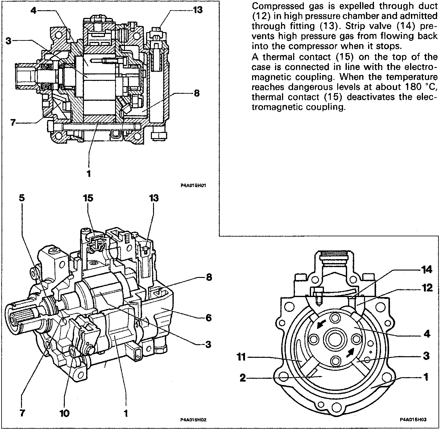
Compressed gas is expelled through duct (12) in high pressure chamber and admitted through fitting (13). Strip valve (14) prevents high pressure gas from flowing back into the compressor when it stops.
A thermal contact (15) on the top of the case is connected in line with the electromagnetic coupling. When the temperature reaches dangerous levels at about 180 °C, thermal contact (15) deactivates the electromagnetic coupling.
Parts & tools for this job For 1995 Fiat Bravo
- TOOLTorque wrenchSearch: 3/8 inch torque wrench
- TOOLSocket setSearch: socket set metric
- BOOKHaynes manualSearch: Haynes manual Fiat Bravo
Links open Amazon search results in a new tab. As an Amazon Associate I earn from qualifying purchases.