
Operation (page 2 of 2)
- Make
- Fiat
- Model
- Bravo /Brava (182) Factory Service Manual
- Year
- 1995–2001
- Section
- Compressor
Flow control is achieved via an electropneumatic mechanism built into the compressor. This by-passes part of the gas in the compression stage to the intake, i.e. the low pressure chamber.When activated, this system, allows compressor output to be reduced to about 17% of the total with the engine at 1000/min.
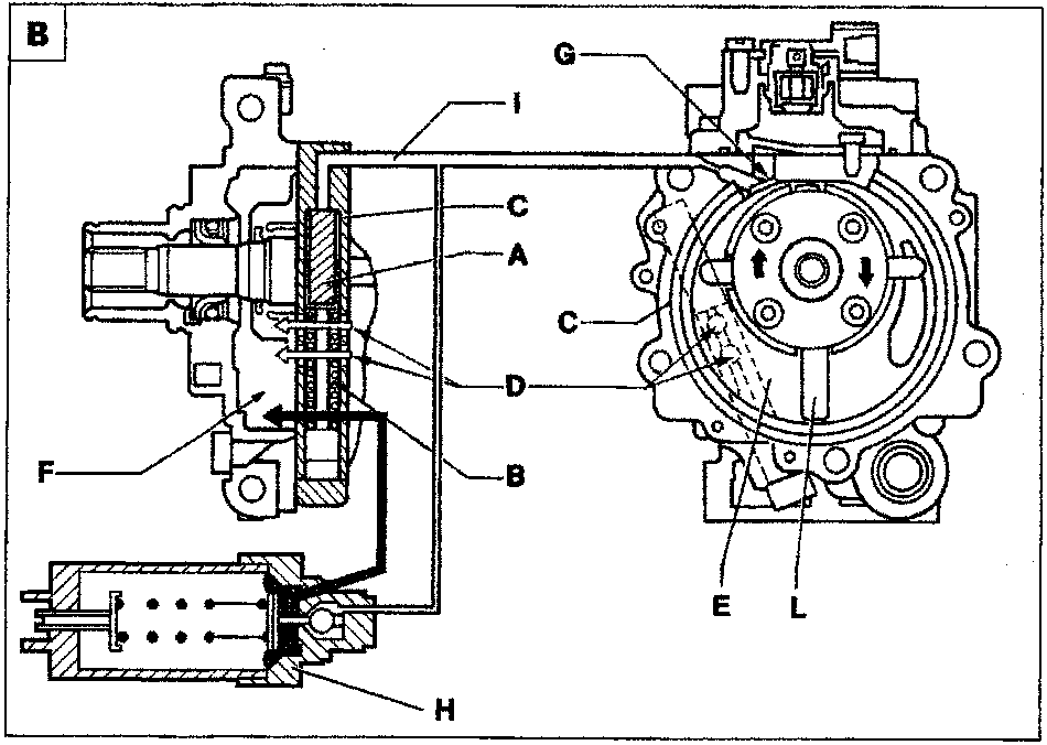
The mechanism consists of a piston (A) that slides through cylinder (C) countered by spring (B). When the piston is positioned as shown in fig. A it blocks holes (D) that bring compartment (E; in which gas compression begins) into communication with low pressure chamber (F). Viceversa, when piston (C) is in the position in fig. B, holes (D) are in communication. The piston is operated by a small proportion of the gas under pressure, taken up by duct (I) that communicates with calibrated holes (G). The mechanism is governed by automatic pressure regulator (H), which intervenes according to pressure in compressor low pressure chamber (F). This pressure is directly proportional to evaporator outlet fluid properties. High pressure in chamber (F) thus brings about high evaporator outlet temperature. Low pressure brings about low temperature.
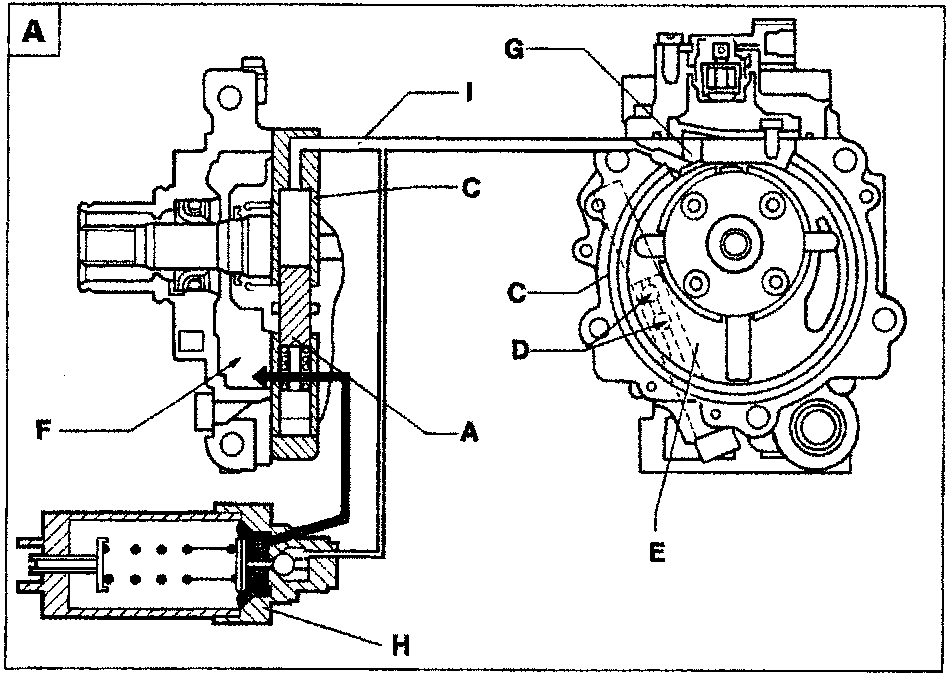
The pressure regulator consists of a ball valve controlled by reference pressure (chamber F), countered by a spring. When reference pressure is high, this overcomes spring load and the valve remains closed. Gas pressure acts on piston (A) to restore it to the position in figure A.
Holes (D) are cut off and gas compression begins in chamber (E) as described in the previous pages.
When reference pressure is too low to overcome spring load, ball valve opens (Fig. B) to allow gas under pressure in duct (I) and cylinder (C) to flow into low pressure chamber (F). Piston (A) is therefore pushed into rest position by spring (B) to open up by-pass holes (D). In this way, part of the gas in chamber (E -at the compression stage) is able to flow into the low pressure chamber (F), until vane (L), has passed holes (D).
By reducing the quantity of gas in chamber (E), compressor output is also be reduced to about 17%.
Parts & tools for this job For 1995 Fiat Bravo
- TOOLTorque wrenchSearch: 3/8 inch torque wrench
- TOOLSocket setSearch: socket set metric
- BOOKHaynes manualSearch: Haynes manual Fiat Bravo
Links open Amazon search results in a new tab. As an Amazon Associate I earn from qualifying purchases.