
Compressor
- Make
- Fiat
- Model
- Bravo /Brava (182) Factory Service Manual
- Year
- 1995–2001
- Section
- Heating/ventilation system › Compressor
50 Auxiliary unitsCompressor
COMPRESSOR
Removing
Disconnect terminal from battery negative connection and drain heating/ventilation system as described previously. Then proceed as follows:
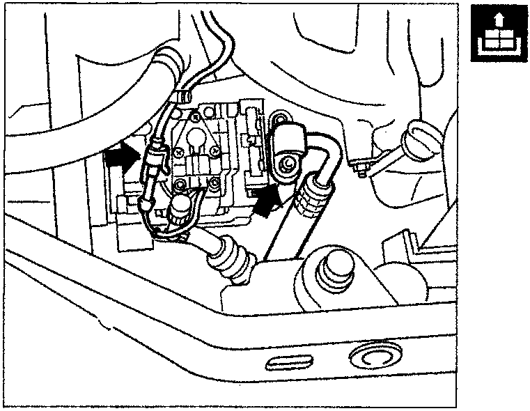
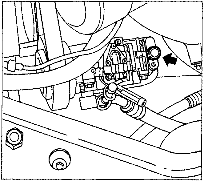
- disconnect connector and undo electrical wiring;
- unscrew screw indicated and disconnect compressor delivery duct wiring;
- seal pipe and compressor duct ends using sealing plugs;
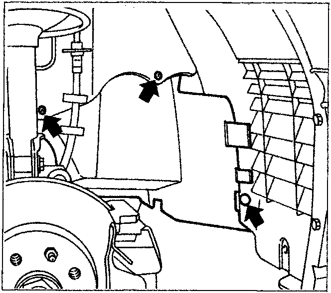
- raise the vehicle and remove the right front wheel;
- remove the clip and unscrew bolts shown in figure, which retain wheel arch guard to body;
Parts & tools for this job For 1995 Fiat Bravo
- TOOLA/C manifold gauge setSearch: AC manifold gauge set
- TOOLUV leak detection kitSearch: AC UV leak detection kit
- PARTCabin filterSearch: Fiat Bravo 1995 cabin filter
Links open Amazon search results in a new tab. As an Amazon Associate I earn from qualifying purchases.