
Checking diodes (page 2 of 2)
- Make
- Fiat
- Model
- Bravo /Brava (182) Factory Service Manual
- Year
- 1995–2001
- Section
- Recharging
55 Electrical systemChecking diodes · page 2 of 2
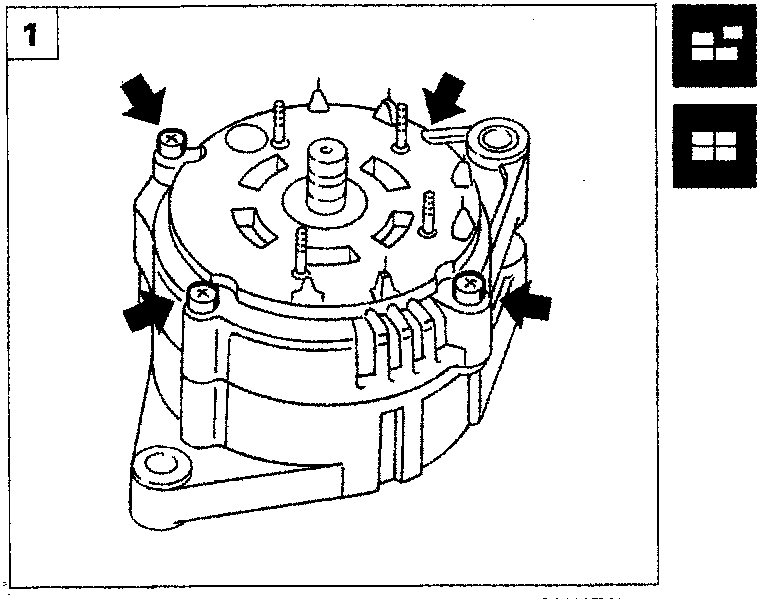
- Undo the bolts shown fixing the alternator assembly.
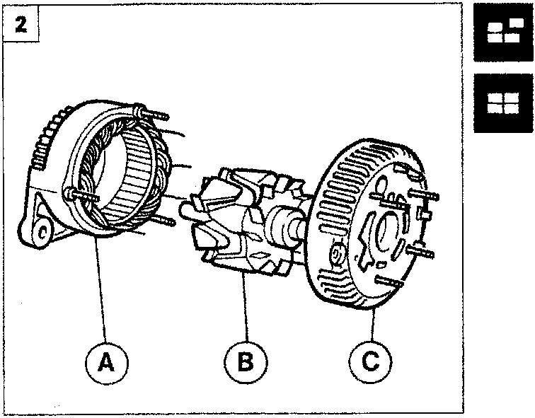
- Dismantle the following alternator components:
- A. Rear support plate with stator windings
- B. Rotor
- C. Front support plate
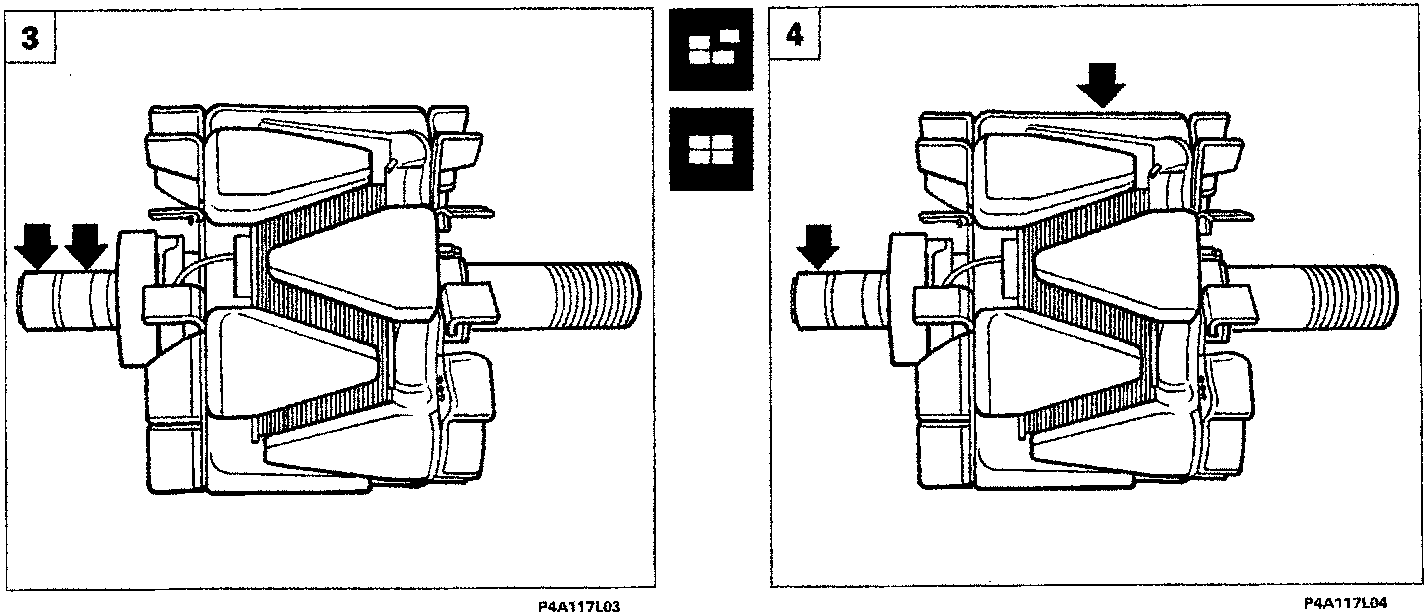
- Checking inductor (rotor) winding resistance at the slip rings
- Place the two probes of an ohmmeter (set on a scale of Ω x 1) in contact with the rotor slip rings (shown by the arrows): the instrument reading should show a certain resistance value.
NOTE If the resistance value is infinite (broken circuit)rrotto), then the rotor has to be replaced.
- Checking stator winding insulation
- Place the two probes of an ohmmeter (set on a scale of Ω x 1) in contact with the windings and the stator casing, respectively;
- the resistance reading on the instrument should be infinite, if this is not the case replace the rotor.
Parts & tools for this job For 1995 Fiat Bravo
- TOOLDigital multimeterSearch: automotive digital multimeter
- PARTAssorted fuse kitSearch: car fuse assortment kit
- TOOLWire crimper and connector kitSearch: wire crimper connector kit
Links open Amazon search results in a new tab. As an Amazon Associate I earn from qualifying purchases.