
Electrical equipment
- Make
- Fiat
- Model
- Grande Punto Factory Service Manual
- Year
- 2005–2012
- Section
- Instrument/gauge electrical circuits › Electrical equipment
ELECTRICAL EQUIPMENT
General specifications
The technology used for the electrical equipment on this model is based on the complex structure known as "Family 1" used for the first time on a FIAT model.
The "Family 1" structure takes the following regional topological approach to improve the system: each control unit (electronic or electromechanical) is located in a centre of gravity position in relation to the functions managed.
This allows the power and signal distribution system to be minimised. This is also made possible through extensive use of serial communication networks that allow us to overcome problems of space-saving, reliability, weight and cost.
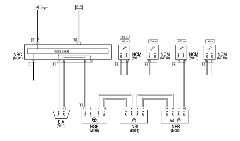
The structure consists of two CAN communication networks which connect nodes belonging to two different areas (vehicle dynamic control) and on board information/bodywork functions and a complementary serial line (LIN bus).
The architecture developed is compatible with various user interface solutions (control arrangement, information allocation and display method).
The electrical protection (fuses) and the relays are grouped together in the power distribution junction units located in the engine compartment and the dashboard. These junction units also act as connections for the various wiring and electrical distribution.
To produce a minimum number of wiring families, each circuit has a section coupling that should maintain the same position inside the coupling, irrespective of the trim level; the position and the type of the coupling on the vehicle should also not depend on the trim level.
To safeguard the modular nature of the wiring the inlets/outlets for each junction unit should not differ according to the trim level/engine type, the position of the connector or the cable/terminal/connector interface.
Fuse and relay holder unit
There are various types of power distribution units on this model produced using 3 different types of technology:
- Power PCB;
- Sheared circuit;
- Wiring with sheared circuit.
More specifically, there is:
- Body Computer Node Junction Unit (M001), produced with Power PCB
- Engine Compartment Junction Unit (B001), produced with sheared circuit
- Fuse Junction Unit on positive battery pole (B099), produced with sheared circuit
- Optional Fuse Junction Unit on positive battery pole (B098), produced with sheared circuit
- Luggage Compartment Junction Unit (B045), with sheared circuit wiring
Electronic compnents
The "Family 1" structure is composed of the elements listed in the table below:
| Description | Wiring diagram code |
|---|---|
| Tyre Pressure Monitoring Control Unit | M047 |
| Parking Sensor Node | M084 |
| Hifi audio amplifier | P049 |
| Body Computer Node | M001 |
| Instrument Panel Node | E050 |
| Radio Receiver Node | P020 |
| Bluetooth Convergence Node | M162 |
| Rain Sensor Control Unit | K085 |
| Sun Roof Control Unit | D045 |
| Air Bag Node | M060 |
| Robotized gearbox node | M054 |
| Climate Control Node | M070 |
| Engine Management Node | M010 |
| Braking System Node | M050 |
| Slewing Sensor Node | K074 |
| Electric steering node | M086 |
| Additional Heater Node | M075 |
User control modules
The "Family 1" structure integrates user controls in the switch carrier modules.
The list of modules is in the table together with the rest of the controls.
| Description | Wiring diagram code |
|---|---|
| Front/rear door electric window control passenger side | H050 / H053 / H054 |
| Brake light switch | I030 |
| Steering column switch unit control module | H005 |
| Switch on Clutch | I0031 |
| Control Panel on driver''s front Door | H044 |
| Centre Control Panel | H090 |
| Left Control Panel | H091 |
| Gear control lever | H037 |
| Controls on the steering wheel for the horn and audio/telephone systems | D047 |
Network architecture
The structure comprises two CAN communication networks connected by a gateway for transferring shared information:
- BCAN (low speed: 50Kbit) for managing standard bodywork/infotelematic functions
- CCAN (high speed: 500 Kbit) for the dynamic control of the vehicle
The gateway for communication between the CCAN and BCAN is located in the Body Computer.
There is also an LIN communication serial line between the Body computer control unit and the control unit on the rain sensor: in this case the Body computer node has a gateway function between the LIN serial line and the CANs.
Ccan
Bcan
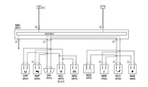
For the first time on a Fiat model the fault diagnosis of the nodes is carried out using a protocol on the CAN (ISO 14229).
Diagnostic structure
The position of the diagnostic structure, for both control units that are integrated in the CAN (nodes) and for those that do not have a CAN interface, is summarized in the table below:
| System / node | Bus | Diagnosis | Communication |
|---|---|---|---|
| Tyre Pressure Control Unit | BCAN | Yes | BCAN |
| Audio amplifier | No | ||
| Rain Sensor Control Unit | LIN | No | |
| Sun Roof Control Unit | No | ||
| Air Bag Node | BCAN | Yes | BCAN |
| Body Computer Node | BC CAN | Yes | BC CAN |
| Climate Control Node | BCAN | Yes | BCAN |
| Bluetooth Convergence Node | BCAN BC CAN | Yes | BCAN BC CAN |
| Instrument Panel Node | BCAN | Yes | BCAN |
| Radio Receiver Node | BCAN | No | |
| Parking Sensor Node | BCAN | Yes | BCAN |
| Additional Heater Node | BCAN | Yes | BCAN |
| Engine Management Node | CCAN | Yes | CCAN |
| Robotized gearbox node | CCAN | Yes | CCAN |
| Braking Node | CCAN | Yes | CCAN |
| Electric steering node | CCAN | Yes | CCAN |
| Slewing Sensor Node | CCAN | No |
Some control units and nodes are designated as "not having fault diagnosis" even though they have an autodiagnostic function (e.g. Rain Sensor Control Unit) which is because they do not have a diagnostic protocol and any errors are detected through the fault diagnosis of other control units (e.g. Body Computer).
Diagnostic connector
On this vehicle the 16-way diagnostic socket is not integrated in the Body Computer but is located to the left of the dashboard, in front of the actual Body Computer.
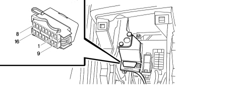
The diagnostic equipment (Examiner or other instruments) is connected to it by means of a special adaptor known as "MPX 97". This adaptor allows the system to which the autodiagnostic equipment is being connected to be selected.
Diagnostic socket connections
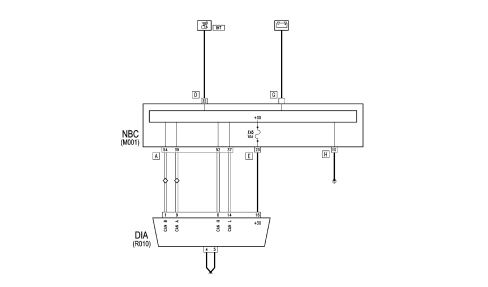
Wiring specifications
The wiring specifications and design features are:
- The use of unipolar cables that conform to all thermal and mechanical use grades (including the special conductors vital in critical application areas).
- Terminals with high yield resistance.
- The creation of multiple couplings using short circuiting connectors (joint connectors) or ultrasound welding protected by a thermal shrinkage tube.
- Earths produced by sealed type components (joint connectors) for engine compartment earths, open for those in the passenger compartment; eyelets to be attached for individual earths; eyelets for welding technology.
- The use of screened or twisted cables for particular functions.
- Complete protection of the wiring through corrugated tubes, plating, foam, polyvinyl chloride tubes, covers, ducts, etc.
- The complete use of secondary locks on connectors.
- Connection safety through the use of low load connectors, audible catches, inertia lock.
- Fastening of shunt connectors so that the connections are never the source of noise or interference.
- All connectors are clearly numbered on the cable introduction side to facilitate the identification of the position of the conductors.
- There are either "PUR" or pressed seals with a siphon at junctions with panels to prevent the cable loom from fraying or deteriorating.
- With the use of these seals the cables can be positioned in such a way that they do not slip out or lose their seal in relation to the panel.
- Thermal grades: all the wiring components have been selected taking the maximum operating temperatures into consideration.
- There are corrugated tubes and accessories on the wiring where the cable loom needs protection against thermomechanical and chemical factors.
MAIN NETWORK NODES
Engine compartment junction unit
The engine compartment junction unit is a junction unit with sheared circuits installed in a sealed container located in the engine compartment in the area of the left light cluster that houses the fuses and relays and performs the function of protecting the electrical loads.
Location of relays and fuses
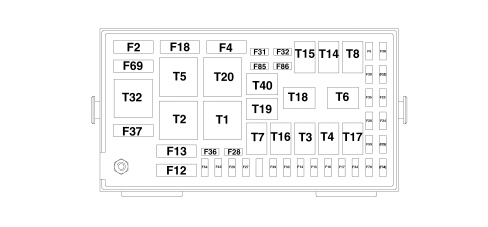
On the more complete version the engine compartment control unit protect the electrical system via the following fuses:
| WIRING DIAGRAM CODE | serigraphy on junction unit | protected circuit | amp. | TYPE |
|---|---|---|---|---|
| F2 | 01 | Body Computer | 60 | MAXI |
| F4 | 10 | Engine ABS | 40 | MAXI |
| F5 | 53 | ABS solenoid valves | 30 | mini |
| F12 | 09 | Motor fan (low and medium speed) | * | MAXI |
| F13 | 08 | Motor fan (high speed) | ** | MAXI |
| F14 | 38 | Left dipped headlamp | 10 | mini |
| F15 | 39 | Right dipped headlamp | 10 | mini |
| F16 | 40 | Left main beam headlamp | 10 | mini |
| F17 | 41 | Right main beam headlamp | 10 | mini |
| F18 | 05 | Vehicle interior fan | 40 | MAXI |
| F20 | 47 | Engine management control unit | 7,5 | mini |
| F23 | 50 | Gear lever and robotized gearbox control unit | 7,5 | mini |
| F24 | 48 | Climate control system controls, climate control system control unit, window opening controls, mirror adjustment | 7,5 | mini |
| F25 | 46 | Spare | mini | |
| F27 | 34 | Secondary loads engine management (Lambda sensor, EGR, canister, etc.) | 15 | mini |
| F28 | 30 | Primary loads engine management (coils, injectors, etc.) | 15 | mini |
| F29 | 33 | Engine management control unit | 10 | mini |
| F30 | 51 | Fuel pump | 15 | mini |
| F31 | 25 | Fog light | 15 | mini |
| F32 | 27 | Headlamp washers | 30 | mini |
| F33 | 37 | Horns | 15 | mini |
| F34 | 42 | Compressor engagement | 7,5 | mini |
| F35 | 49 | Starting relay | 30 | mini |
| F36 | 29 | Bipower system valves | 7,5 | mini |
| F37 | 04 | Robotized gearbox pump | 30 | MAXI |
| F38 | 54 | Climate control system controls, climate control system control unit | 7,5 | mini |
| F39 | 36 | Gear lever and robotized gearbox control unit | 15 | mini |
| F43 | 32 | Engine management control unit | 7,5 | mini |
| F54 | 31 | Cigar lighter socket 12V | 20 | mini |
| F59 | 45 | Reversing switch, flow meter, water in diesel filter sensor, heater plugs (JTD only) | 10 | mini |
| F69 | 02 | Rear windscreen defrosting | 30 | MAXI |
| F70 | 43 | Exterior rear view mirrors defrosting | 10 | mini |
| F85 | 26 | Right front electric window | 20 | mini |
| F86 | 28 | Left front electric window | 20 | mini |
| FS2 | 52 | Spare | mini | |
| FS4 | 44 | Spare | mini |
(*) 20A, 30A or 40 A, depending on the version
(**) 30A, 40A or 60 A, depending on the version
The following relays are housed in the engine compartment control unit:
| WIRING DIAGRAM CODE | serigraphy on junction unit | protected circuit | amp. | TYPE |
|---|---|---|---|---|
| T1 | 12 | Motor fan (low speed) | 50 | maxi |
| T2 | 07 | Motor fan (high speed) | 50 | maxi |
| T3 | 19 | Dipped headlamps | 20 | micro |
| T4 | 21 | Main beam headlamps | 20 | micro |
| T5 | 06 | Ignition-operated starting excluded power supply | 50 | maxi |
| T6 | 23 | Ignition-operated power supply | 30 | micro |
| T7 | 15 | Engine management power supply | 30 | micro |
| T8 | 22 | Fuel pump | 20 | micro |
| T14 | 20 | Fog light | 20 | micro |
| T15 | 17 | Headlamp washers | 30 | micro |
| T16 | 16 | Horns | 20 | micro |
| T17 | 24 | Compressor engagement | 20 | micro |
| T18 | 18 | Starting-controlled power supply | 30 | micro |
| T19 | 14 | Bipower system valves (N.C.) | 20 | micro |
| T20 | 11 | Motor fan (medium speed) | 50 | maxi |
| T32 | 03 | Defrosting | 40 | maxi |
| T40 | 13 | Front electric windows | 30 | micro |
Engine compartment junction unit internal wiring diagram
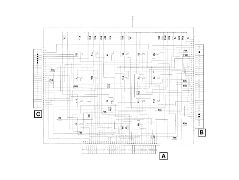
Connections rear view
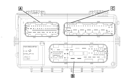
- B01A 36 pin connector, engine services cable
- B01B 42 pin connector, rear cable
- B01C 28 pin connector, crossmember cable
- B01X 1 pin connector power supply (on front section)
Junction unit on battery
It connects the battery terminal to the starter motor lead, to the engine compartment junction unit and to the first level power fuses that protection the luggage compartment junction unit power supply, the electric steering, the heater plugs control unit (JTD versions) or the robotized gearbox pump (versions with robotized gearbox).
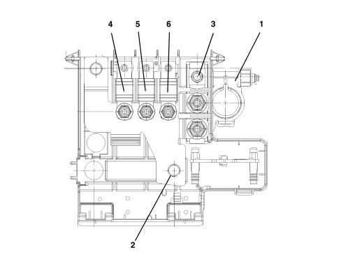
1 - Positive battery terminal
2 - Connecting cable to starter motor
3 - Connecting cable to engine compartment junction unit
4 - Fuse F3
5 - Fuse F6
6 - Fuse F7
| WIRING DIAGRAM CODE | protected circuit | amp. | TYPE |
|---|---|---|---|
| F3 | luggage comparment junction unit | 60 | MIDI |
| F6 | electric steering | 70 | MIDI |
| F7 | heater plugs JTD versions | 50 | MIDI |
| F7 | gearbox pump robotized gearbox versions | 30 | MIDI |
Optional fuses junction unit
There are two additional fuses, located next to the junction unit on the battery, for versions which have an additional heater (JTD only): F74 (30A) and F76 (50A).
Luggage compartment junction unit
The rear junction unit is located in the luggage compartment, on the left rear side panel.
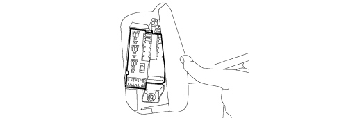
Location of relays and fuses
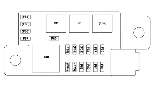
On the more complete version the luggage compartment junction unit protects the electrical system via the following fuses:
| WIRING DIAGRAM CODE | serigraphy on junction unit | Protected circuit | Amp. | TYPE |
|---|---|---|---|---|
| F55 | 01 | spare | mini | |
| F88 | 02 | spare | mini | |
| F56 | 03 | spare | mini | |
| F57 | 04 | driver''s front seat lumbar adjustment motor | 10 | mini |
| F80 | 05 | luggage compartment current socket | 20 | mini |
| F84 | 06 | spare | mini | |
| F75 | 07 | spare | mini | |
| F68 | 08 | driver''s front seat heating | 10 | mini |
| F83 | 09 | passenger side front seat heating | 10 | mini |
| F64 | 10 | electric window in right rear door | 20 | mini |
| F81 | 11 | electric window in left rear door | 20 | mini |
| FS8 | 12 | spare | mini | |
| F82 | 13 | spare | mini | |
| F52 | 14 | spare | mini | |
| F62 | 15 | tyre inflation pressure monitoring control unit | 10 | mini |
| F67 | 16 | hifi system subwoofer amplifier | 20 | mini |
| F50 | 17 | electric sun roof | 20 | mini |
The following relays are housed in the luggage compartment control unit:
| WIRING DIAGRAM CODE | serigraphy on junction unit | protected circuit | amp. | TYPE |
|---|---|---|---|---|
| T30 | 01 | Ignition-operated starting excluded power supply | 50 | maxi |
| T31 | 02 | driver''s front seat heating | 20 | micro |
| T35 | 03 | passenger side front seat heating | 20 | micro |
| TS2 | 04 | spare | 20 | micro |
Luggage compartment junction unit internal wiring diagram
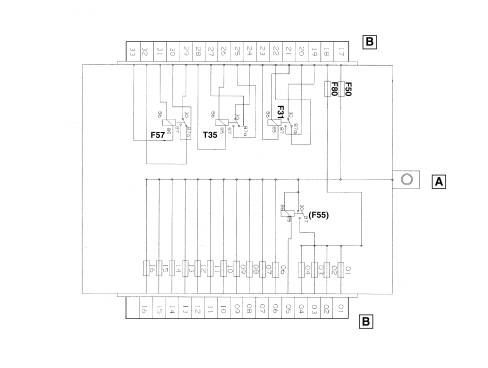
Connections rear view
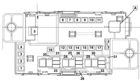
-B45A 1 pin connector power supply
- B45B connections inserted directly in the rear wiring (the numbers of the pins are stamped on the actual junction unit)
The lugage compartment junction unit is wired to the rear cable and does not have connections that can be disconnected; it can only be replaced by disconnecting the individual terminals.
Op. 5505A14 SUPPLEMENTARY JUNCTION BOX IN LUGGAGE COMPARTMENT - R.R
Body computer node
The Body Computer Node is an electrical/electronic component that carries out both the function of distributing the electric power (power PCB) and the function of managing the vehicle serial networks and functions of the "Family 1" structure (interior/exterior lighting, immobilizer, fault diagnosis, wiper, heated rear windscreen, door and boot locking/unlocking, fuel level, management and acquisition of key status) and houses the gateway between the BCAN and CCAN and between the LIN and BCAN.
The interfaces for the remote control and immobilizer RF aerials are at the Body Computer.
Connections front/rear view
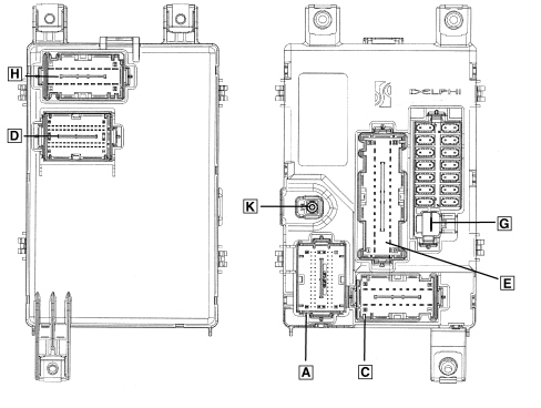
- M01A 60 pin connector, rear cable
- M01C 20 pin connector, rear cable
- M01D 60 pin connector, dashboard cable
- M01E 32 pin connector, rear cable
- M01G 1 pin connector, rear cable power supply
- M01H 20 pin connector, dashboard cable
- M01K 1 pin connector, rear cable
There is a PCB inside the Body Computer, next to the electronic section, that performs the function of distributing the electrical power (PCB power); this function is carried out by means of micro relays incorporated in the actual PCB (which therefore cannot be replaced); there are fuses on the output lines for the various consumers located on the outside of the Body Computer casing as illustrated in the diagram.
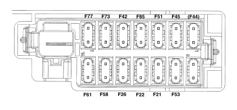
The following fuses are located on the most complete version of the Body Computer:
| WIRING DIAGRAM CODE | serigraphy on junction unit | protected circuit | amp. | TYPE |
|---|---|---|---|---|
| F44 | 1 | spare | mini | |
| F45 | 2 | instrument panel, EOBD diagnostic socket | 10 | mini |
| F51 | 3 | radio, Bluetooth convergence control unit, preparation for navigator | 15 | mini |
| F85 | 4 | ignition switch power supply | 7,5 | mini |
| F42 | 5 | electric windscreen/rearscreen washer pump | 20 | mini |
| F73 | 6 | boot opening actuator | 15 | mini |
| F77 | 7 | central locking motor actuators | 20 | mini |
| 8 | spare | mini | ||
| F53 | 9 | front courtesy light, rear courtesy light, luggage compartment light, door courtesy lights, sun visor lights | 10 | mini |
| F21 | 10 | electric steering control unit | 7,5 | mini |
| F22 | 11 | instrument panel, brake lights switch, clutch pedal switch | 7,5 | mini |
| F26 | 12 | ABS control unit, slewing sensor, brake switch | 7,5 | mini |
| F58 | 13 | air bag control unit | 10 | mini |
| F61 | 14 | left control panel lighting, centre control panel, controls on steering wheel lighting, front seat heating controls, sun roof control unit, tyre inflation pressure monitoring control unit, Bluetooth convergence control unit, parking assistance control unit, preparation for radio and navigator | 7,5 | mini |
CONNECTOR PIN OUT
| Conn. | Pin | Function |
|---|---|---|
| A | 1 | ignition operation relay T6 |
| A | 2 | control lighting (N.C.) |
| A | 3 | fog lights relay control T14 |
| A | 4 | ignition operated starting excluded relay T30 |
| A | 5 | VSO output (N.C.) |
| A | 6 | headlamp washer relay T15 |
| A | 7 | door open signal for robotized gearbox |
| A | 8 | hazard warning lights LED (N.C.) |
| A | 9 | horn relay control T16 |
| A | 10 | main beam headlamps relay control T4 |
| A | 11 | electric windows power supply enablement |
| A | 12 | heated rear windscreen LED operation |
| A | 13 | ignition operated starting excluded relay T5 |
| A | 14 | N.C. |
| A | 15 | N.C. |
| A | 16 | dipped headlamps relay control T3 |
| A | 17 | boot handle signal (N.C.) |
| A | 18 | hazard warning lights LED (N.C.) |
| A | 19 | brake pedal signal (N.C. switch) |
| A | 20 | heated rear windscreen signal |
| A | 21 | brake fluid level signal |
| A | 22 | windscreen wiper cam signal |
| A | 23 | inertia switch signal N.O. |
| A | 24 | rearscreen wiper cam signal |
| A | 25 | clutch pedal signal (N.C.) |
| A | 26 | alarm signal (N.C.) |
| A | 27 | brake pad wear signal |
| A | 28 | brake pedal signal (N.O. switch) |
| A | 29 | driver''s front door switch |
| A | 30 | passenger front door switch (N.C.) |
| A | 31 | N.C. |
| A | 32 | RF aerial earth (N.C.) |
| A | 33 | N.C. |
| A | 34 | N.C. |
| A | 35 | A - BUS roof (N.C.) |
| A | 36 | CAN-L (N.C.) |
| A | 37 | CAN-L |
| A | 38 | CAN-L |
| A | 39 | CAN-A |
| A | 40 | fuel level sensor earth |
| A | 41 | left rear door open signal |
| A | 42 | boot open signal (N.C. switch) |
| A | 43 | handbrake switch |
| A | 44 | N.C. |
| A | 45 | fuel level sensor signal |
| A | 46 | heated rear windscreen relay feed T32 |
| A | 47 | RF aerial signal (N.C.) |
| A | 48 | N.C. |
| A | 49 | A/C request signal |
| A | 50 | serial line (N.C.) |
| A | 51 | CAN-H (N.C.) |
| A | 52 | CAN-H |
| A | 53 | CAN-H |
| A | 54 | CAN-B |
| A | 55 | right rear door open signal |
| A | 56 | front passenger door open signal |
| A | 57 | front driver''s door open signal |
| A | 58 | N.C. |
| A | 59 | outside temperature sensor earth |
| A | 60 | outside temperature sensor signal |
| C | 1 | right front direction indicator |
| C | 2 | left door light |
| C | 3 | front courtesy light control |
| C | 4 | right door light |
| C | 5 | N.C. |
| C | 6 | N.C. |
| C | 7 | right rear side light |
| C | 8 | N.C. |
| C | 9 | left front direction indicator |
| C | 10 | right side direction indicator |
| C | 11 | right rear direction indicator |
| C | 12 | rear fog lamp |
| C | 13 | front side lights |
| C | 14 | no. plate lights |
| C | 15 | right brake light |
| C | 16 | left brake light |
| C | 17 | left rear side light |
| C | 18 | centre brake light (third brake light) |
| C | 19 | left side direction indicator |
| C | 20 | left rear direction indicator |
| D | 1 | CODE aerial signal |
| D | 2 | outside aerial earth (N.C.) |
| D | 3 | Driving Program Led 1 (N.C.) |
| D | 4 | A - BUS door (N.C.) |
| D | 5 | CAN-B |
| D | 6 | CAN-H (N.C.) |
| D | 7 | CAN-L (N.C.) |
| D | 8 | tailgate actuator control (N.C.) |
| D | 9 | VSO output (N.C.) |
| D | 10 | hazard warning lights LED operation |
| D | 11 | door status LED operation |
| D | 12 | heated rear windscreen LED operation (N.C.) |
| D | 13 | START/STOP button lighting (N.C.) |
| D | 14 | switch lighting (N.C.) |
| D | 15 | N.C. |
| D | 16 | CODE aerial earth |
| D | 17 | outside aerial power supply (N.C.) |
| D | 18 | Driving Program Led 2 (N.C.) |
| D | 19 | N.C. |
| D | 20 | CAN-A |
| D | 21 | CAN-H (N.C.) |
| D | 22 | CAN-L (N.C.) |
| D | 23 | hazard warning lights switch signal |
| D | 24 | Boot handle switch (N.C.) |
| D | 25 | boot opening actuator control |
| D | 26 | Boot open switch (N.C.) |
| D | 27 | DRL control (N.C.) |
| D | 28 | CITY function signal |
| D | 29 | rearscreen wiper signal from steering column switch unit |
| D | 30 | fog lights switch signal |
| D | 31 | AVV (starting) command (50) from ignition switch |
| D | 32 | MAR (ON) command (15) from ignition switch |
| D | 33 | Driving Program Led 3 (N.C.) |
| D | 34 | reference earth for steering column switch unit |
| D | 35 | reference earth for controls on the steering wheel |
| D | 36 | N.C. |
| D | 37 | main beam headlamps signal from steering column switch unit |
| D | 38 | side lights / dipped headlamps signal from steering column switch unit |
| D | 39 | door locking/unlocking switch signal |
| D | 40 | wiper intermittent adjustment signal (N.C.) |
| D | 41 | Cruise Control signal from steering column switch unit |
| D | 42 | reference earth for left dashboard controls |
| D | 43 | N.C. |
| D | 44 | rear fog lamp switch signal |
| D | 45 | radiator fluid level signal (N.C.) |
| D | 46 | N.C. |
| D | 47 | N.C. |
| D | 48 | ignition switch power supply |
| D | 49 | reference earth for controls in the centre of the dashboard |
| D | 50 | controls signal to steering wheel 2 |
| D | 51 | direction indicators signal from steering column switch unit |
| D | 52 | controls signal to steering wheel 3 |
| D | 53 | controls signal to steering wheel 1 |
| D | 54 | windscreen wiper signal from steering column switch unit |
| D | 55 | windscreen washer signal from steering column switch unit |
| D | 56 | N.C. |
| D | 57 | Body Computer earth (N.C.) |
| D | 58 | heated rear windscreen operation (N.C.) |
| D | 59 | A/C request signal (N.C.) |
| D | 60 | screen washer fluid level signal (N.C.) |
| E | 1 | driver''s door opening command (N.C.) |
| E | 2 | fuel flap opening command (N.C.) |
| E | 3 | windscreen/rearscreen washer pump operation |
| E | 4 | left rear courtesy light operation (N.C.) |
| E | 5 | rear / right rear courtesy light operation |
| E | 6 | parking sensors control unit power supply (ignition-operated), tyre inflation pressure control unit, bluetooth convergence control unit, sun roof; seat controls lighting, |
| E | 7 | rain sensor (ignition controlled) power supply |
| E | 8 | brake pedal (N.O. switch) (ignition controlled) power supply |
| E | 9 | clutch pedal (ignition controlled) power supply |
| E | 10 | right DRL (N.C.) |
| E | 11 | climate control system controls lighting |
| E | 12 | left DRL (N.C.) |
| E | 13 | N.C. |
| E | 14 | windscreen/rearscreen washer pump operation |
| E | 15 | rearscreen wiper control |
| E | 16 | windscreen wiper control (high speed) |
| E | 17 | door locking control (locking/unlocking motors) |
| E | 18 | door locking control (dead lock motors) |
| E | 19 | door locking control (shared motors) |
| E | 20 | controlled power supply relay T40 |
| E | 21 | ABS control unit (ignition controlled) power supply |
| E | 22 | brake pedal (N.C. switch) (ignition controlled) power supply |
| E | 23 | slewing sensor (ignition controlled) power supply |
| E | 24 | parking sensor control unit (ignition controlled) power supply |
| E | 25 | front courtesy light timed power supply |
| E | 26 | rear courtesy light timed power supply |
| E | 27 | sun visor lights timed power supply |
| E | 28 | boot courtesy light timed power supply |
| E | 29 | diagnostic socket (direct) power supply |
| E | 30 | boot opening actuator control |
| E | 31 | cigar lighter lighting |
| E | 32 | windscreen wiper operation (low speed) |
| K | 1 | RF aerial signal |
| K | 2 | RF aerial earth |
| G | 1 | Body Computer (direct) power supply |
| H | 1 | radio (direct) power supply |
| H | 2 | control panel (direct) power supply |
| H | 3 | diagnostic socket (direct) power supply (N.C.) |
| H | 4 | (ignition controlled) power supply (N.C.) |
| H | 5 | control panel (ignition controlled) power supply |
| H | 6 | parking sensor control unit (ignition controlled) power supply (N.C.) |
| H | 7 | Air Bag (ignition controlled) power supply |
| H | 8 | N.C. |
| H | 9 | N.C. |
| H | 10 | Body Computer power earth |
| H | 11 | (direct) power supply (N.C.) |
| H | 12 | bluetooth convergence control unit (direct) power supply |
| H | 13 | display (direct) power supply (N.C.) |
| H | 14 | ELS (direct) power supply (N.C.) |
| H | 15 | glove compartment light timed power supply |
| H | 16 | centre dashboard controls lighting |
| H | 17 | left dashboard controls lighting |
| H | 18 | steering wheel controls lighting |
| H | 19 | radio controls lighting |
| H | 20 | N.C. |
CAN NODE OPERATION
Instrument panel node
The Instrument Panel Node is an electronic component connected to the BCAN; it acquires several user commands and manages the SETUP menu and the control of the headlamp alignment.
There are also interfaces with other vehicle systems (engine management) at the connector.
For more details
Steering column switch unit control module
The steering column switch unit module includes the exterior lighting controls (on the lights lever on the left) and the windscreen/rearscreen washing and wiping controls (on the wiper lever on the right).
The module also houses the trip function and the optional Cruise Control function.
For more details
Op. 5550 WARNING AND MANOEUVRING INDICATORS
Radio receiver node
The Radio Node is an electronic component connected to the BCAN.
There is an interface at the Radio Receiver Node with an external audio amplifier, with the after market CD Changer and with an external module for the management of the GSM (telephone) and GPS (navigation) systems.
For more details
Parking sensor node
The Parking Sensor Node is an electronic components connected to the BCAN which provides driving assistance functions during manoeuvres with reverse gear engaged, detecting any obstacles at the rear. There are interfaces at the parkign sensor node for the sensors in the rear bumper and for the buzzer in the instrument panel node.
Op. 5580H PARKING OBSTACLE DETECTION DEVICE
Clock spring
The clock spring is an interconnecting component incorporated in the steering column switch unit module that guarantees the connection between the dashboard cables, the controls on the steering wheel (audio system and telephone system) and the driver''s Air Bag modules.
For more details
Safety system control unit (air bag)
The safety system interfaces with the crossmember cable assembly (front impact sensor), with the dashboard cable assembly (front loads, BCAN management, power supplies) and with the collection of rear cables (side loads/blinds and pretensioners, side impact sensors, sensors on front seats). There is a specific earth point for the safety system located near the control unit.
For more details
Climate control sytem control unit
The interface with the automatic climate control system manages input/output information via the CAN (information, data).
The climate control system is connected to the rear wiring via a bridge.
The system power earth is connected directly to the climate control unit by the bridge.
For more details
Op. 5040 AIR CONDITIONING CASING AND COMPONENTS
Rain sensor control unit
The rain sensor control unit is an electronic component connected to the Body Computer Node via the LIN serial line and, together with a control on the steering column switch unit module, manages the function of regulating the speed of the windscreen wiper strokes.
The rain sensor control unit is connected via a special bridge located on the interior rear view mirror.
For more details
Op. 5050 SCREEN WASHERS AND HEADLAMP WASH/WIPE
Tyre pressure control unit
The TPMS (tyre pressure monitoring system) control unit is an electronic component connected to the BCAN that manages the monitoring of the inflation pressure of all four tyres.
For more details
Bluetooth convergence control unit
The Bluetooth Convergence control unit is an electronic component connected to the BCAN or to the BCAN and CCAN depending on the version which, when interfaced with the on board radio receiver, allows various entertainment functions:
"C1" basic version: hands-free function with Bluetooth interface for user mobile phone and entertainment (MP3)
"C3" de-luxe version NOT AVAILABLE AT THE LAUNCH OF THE MODEL
Brake pedal switch
This is a switch located on the brake pedal that is connected to the rear wiring. It carries out the function of indicating the brake pedal status to provide the control units that require it with the status of the actual pedal.
It has two contacts (NO + NC) with separate power supplies and the same connection.
The following control units require brake pedal status information:
- Body Computer
- Engine management control unit
- Braking system control unit, two versions: ABS, ESP
- Robotized Gearbox Control Unit, if fitted.
Switch on clutch pedal
The clutch switch is a switch located on the clutch pedal which provides the control units that require information on the clutch pedal status.
Control panel on driver''s front door
The control panel on the driver''s frontn door is a module that includes the various controls on the driver''s front door and it interfaces with the driver''s front door collection of cables.
The control panel receives a power supply for the ideogram lighting and for the correct operation of the controls.
Depending on the trim level, it may contain the following controls:
- Electric front windows control
- Electric rear windows control (if fitted)
- Electric rear windows inhibition control (if fitted) with LED
- Exterior electric mirrors selector
- Exterior electric mirrors joystick
Electric window control on front passenger door
The window control on the front passenger door is connected via the passenger front door collection of cables to provide the command for the window opening motor and receives a power supply for lighting the ideogram and for the correct operation of the actual control.
Electric windows control on rear doors
The control on the left rear door and the right rear door is connected via the collection of cables on the rear door and is acquired by means of electronics inside the electric window motor on the rear door with an automatic raising and lowering function with an anti-crush safety device.
The control receives a power supply for lighting the ideogram and for the correct operation of the control itself from the disinhibiting control located in the control panel in the driver''s front door.
Centre control panel
The control panel is connected via the dashboard cable assembly.
The module houses the following buttons:
- City button for switching the electric steering City function on/off
- ASR off button and warning light (LED in button)
- door locking/unlocking button and LED: the LED has the function of signalling the door locking status with the light on constantly; the same LED has a deterrent function when the vehicle is locked from the outside: in this case it is on intermittently.
- boot opening button
- hazard warning lights button
- ECO button for Economy mode function for versions with robotized gearbox.
Left control panel
The left control panel is a module that incorporates the controls on the outside of the steering wheel and interfaces with the Body Computer Node and the Instrument Panel Node via the collection of dashboard cables.
The left control panel receives a power supply for lighting the ideograms and houses the following controls:
- Fog lights
- Rear fog lamps
- Headlamp alignment corrector
- Mode buttons (regulate different functions in the instrument SETUP function).
Electric steering control unit
The interface with the electric steering system manages input/output information via the following serial line: CCAN (information, data).
REPLACING AND INITIALIZING NETWORK NODES
Some of the CAN nodes are programmed with default settings which the customer will discover on acquiring the vehicle.
The nodes storing this information are the:
- Body Computer;
- Instrument Panel;
- Climate control system control unit.
- Air Bag control unit
- Bluetooth Convergence Control Unit.
If the Body Computer is being replaced, an "identical copy" of the Body Computer must be obtained from the Parts Dept as a V.O.R. order supplying the vehicle chassis number: this copy will contain all the default settings entered when the vehicle was new which are stored in the Parts Dept. database for the vehicle chassis number.
If the Instrument Panel, Climate Control System Control Unit, Air Bag Control Unit or the Bluetooth Convergence Control Unit is being replaced, the Parts Dept. will send a pristine component. once fitted; the initial default data must be transferred to it by carrying out the "PROXI ALIGNMENT" procedure using the Examiner.
If other nodes are being replaced, no initialization operation is required. However, always check that the system has not picked up errors during the removing-refitting operations, etc. using the Examiner.
Battery disconnection
If the battery is disconnected:
- Body Computer
- Instrument Panel
- Climate control system control unit
- Air Bag control unit
- Bluetooth Convergence Control Unit.
They keep the information received and do not need to be initialized after the battery is disconnected, whilst the other nodes lose some or all of the information memorized.
Logistic mode
There is software inside the Body Computer that excludes some of the vehicle electrical loads, except the main functions, known as the LOGISTIC MODE:
The activation of the Logistic Mode guarantees the possibility of starting up the vehicle and driving it without adverse effects in terms of safety even if there is a slight lowering of on board comfort standards and certain functions.
This function, managed by software inside the Body Computer, is used to reduce current absorption due to accidental or deliberate activation of unnecessary loads.
The low consumption power supply mode (Logistic Mode) is activated when vehicles are stored in the period between the end of production and when they are handed over to the final customer and allows battery energy saving when the vehicle is parked, possibly for a long time, before being sold.
The following functions are involved in the activation of the Logistic Mode:
- Central locking and remote control commands
- Electric windows movements
- Radio
- Current socket/cigar lighter
- Climate control
- Additional heater
- Sun roof
- Seat heating
- Switching on of courtesy lights and interior lights
- Switching on of fog lights/rear fog lamps
- Switching on of main beam headlamps
The function should be disabled in the workshop before the vehicle is handed over to the Customer.
Deactivation procedure
The procedure is as follows:
- connect the diagnostic device terminal to the vehicle EOBD socket and turn the ignition ON;
- check that the battery recharging warning light is in flashing mode to indicate that the Logistic Mode low consumption mode is activated;
- deactivate the low consumption supply mode by carrying out the fault diagnosis of the Body Computer node using the Examiner;
the Body Computer node will receive the deactivation command from the diagnostic equipment and, in addition to exiting the low consumption conditions reactivating full operation, it will send the Standard Power command to the CANS (BCAN, CCAN, LIN).
- all the control units involved, on receiving the CAN message, will restore their full operation and send a confirmation message to the Body Computer node.
- delete the error memory in all control units with a diagnostic function.
- carry out a key OFF - key ON.
- check that the battery recharging warning light is on constantly.
Parts & tools for this job For 2005 Fiat Grande Punto
- TOOLDigital multimeterSearch: automotive digital multimeter
- PARTAssorted fuse kitSearch: car fuse assortment kit
- TOOLWire crimper and connector kitSearch: wire crimper connector kit
Links open Amazon search results in a new tab. As an Amazon Associate I earn from qualifying purchases.