
Engine - dismantle and reassemble following operation 1004e10 - wash and check dismantled parts - refit cylinder head an
- Make
- Fiat
- Model
- Grande Punto Factory Service Manual
- Year
- 2005–2012
- Section
- Engine and power unit › Engine - dismantle and reassemble following operation 1004e10 - wash and check dismantled parts - refit cylinder head an
ENGINE - DISMANTLE AND REASSEMBLE FOLLOWING OPERATION 1004E10 - WASH AND CHECK DISMANTLED PARTS - REFIT CYLINDER HEAD AND OIL SUMP - DOES NOT INCLUDE REPAIRS TO CYLINDER HEAD AND AUXILIARY UNIT
Removing
1. Fit the tool on the crankshaft.
| Tool | Description | Function | Validity |
|---|---|---|---|
| 1860815000 | Flange | Crankshaft rotation | 1.9 Multijet |
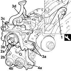
2. Lock the crankshaft using the tool fitted previously for undoing the (left) bolt (2a) and remove the toothed drive pulley (2b).
3. Undo the bolts (3a), (3b) and remove the crankcase front cover with the oil pump incorporated (3c) complete with intake (3d).
4. Undo the bolts and remove the support (4a) complete with moving timing belt tensioner (4b).
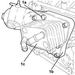
1. Undo the bolts (1a) and remove the engine oil filter mounting (1b) complete with heat exchanger (1c).
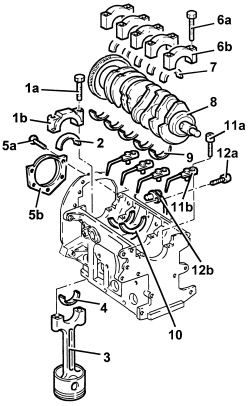
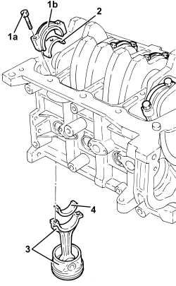
1. Undo the bolts (1a) and remove the connecting rod cap (1b).
2. Remove the lower connecting rod half-bearing.
3. Remove the connecting rod-piston assembly
4. Remove the upper connecting rod half-bearing.
- Carry out the same operations to remove the pistons and connecting rods for the remaining cylinders.
- Remove the tool.
| Tool | Description | Function | Validity |
|---|---|---|---|
| 1860815000 | Flange | Crankshaft rotation | 1.9 Multijet |
5. Undo the bolts (5a) and remove the crankcase rear cover (5b) with the oil seal incorporated.
- Check that the crankshaft endfloat corresponds to the recommended figures using a magnetic base and dial gauge.
| Measurement | Value | Validity |
|---|---|---|
| Crankshaft endfloat (mm) | 0.049 ÷ 0.211 | 1.9 Multijet |
- If the value for the crankshaft endfloat does not correspond with the recommended figures, when refitting, regrind the crankcase seat and use suitable oversize thrust washers.
6. Undo the bolts (6a) and remove the bearing caps (6b).
7. Remove the lower main journal half-bearings.
8. Remove the crankshaft.
9. Remove the upper main journal half-bearings.
10. Remove the thrust washers.
11. Undo the bolts (11a) and remove the jets (11b) from the crankcase.
12. Undo the bolt (12a) and remove the rpm sensor (12b).
- Rotate the crankcase through 90° on the overhaul stand.
- Undo the bolts and remove the crankcase from the mounting, then place it on a special workbench.
- Undo the bolts and remove the intake duct from the oil pump.
Op. 1084B18 ENGINE OIL PUMP, REMOVED - CHECK AT BENCH
Refitting
- Wash the dismantled components.
- Fit the water/oil sealing plugs in the crankcase using suitable fitting tools.
- Lubricate all the mechanical components with engine oil.
- Check that the cylinder head support surface does not have cracks or superficial grooves.
- Check that the planarity of the cylinder head support surface corresponds to the recommended figure; if this is not the case, regrind the cylinder head support surface.
| Measurement | Value | Validity |
|---|---|---|
| Cylinder head support surface flatness (mm) | < 0.1 | 1.2 8v 1.4 8v 1.4 16v 1.9 Multijet |
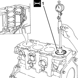
1. Measure the cylinder bore diameter using the diagram illustrated.
| Measurement | Value | Validity |
|---|---|---|
| Cylinder liner diameter - Grade A (mm) | 82.000 ÷ 82.010 | 1.9 Multijet |
| Measurement | Value | Validity |
|---|---|---|
| Cylinder liner diameter - Grade B (mm) | 82.010 ÷ 82.020 | 1.9 Multijet |
| Measurement | Value | Validity |
|---|---|---|
| Cylinder liner diameter - Grade C (mm) | 82.020 ÷ 82.030 | 1.9 Multijet |
- Check that the taper of the cylinder liners/bores is within the recommended limits.
| Measurement | Value | Validity |
|---|---|---|
| Cylinder liner taper (mm) | < 0.005 | 1.9 Multijet |
- Check that the ovality of the cylinder liners is within the recommended limits.
| Measurement | Value | Validity |
|---|---|---|
| Cylinder liner ovality (mm) | < 0.05 | 1.9 Multijet |
1. If the cylinder bore measurements are not within the recommended limits, ream the cylinder bores following the recommended oversizes.
In the case of reaming, all the bores must have the same oversize.
| Measurement | Value | Validity |
|---|---|---|
| Cylinder liner diameter oversize (mm) | 0.1 | 1.2 8v 1.4 8v 1.4 16v 1.3 Multijet 1.9 Multijet |
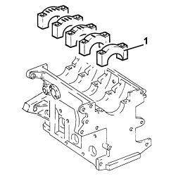
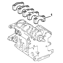
1. Temporarily fit the bearing caps.
The bearing caps have progressively numbered references (from zero to four starting from the front of the engine) which define the fitting position.
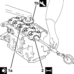
1. Tighten the bearing cap bolts (1a) to the recommended torque using the angular tightening tool (1b).
| Component | Fastening | dia | Value (daNm) | Validity |
|---|---|---|---|---|
| Bearing caps | Bolt | M12 | 2.4 ÷ 2.6 + 100° | 1.9 Multijet |
| Tool | Description | Function | Validity |
|---|---|---|---|
| 1860942000 | Torque wrench | Tighten bolts to torque plus angle |
2. Check that the diameter of the main journal seats is within specified limits.
| Measurement | Value | Validity |
|---|---|---|
| Main journal seat diameter (mm) | 63.705 ÷ 63.718 | 1.9 Multijet |
- Check that there are no deposits or blockages in the crankshaft lubrication ducts.
- Check that the diameter of the main journals corresponds to the recommended figures.
| Measurement | Value | Validity |
|---|---|---|
| Main journal diameter - Category A (mm) | 59.994 ÷ 60.000 | 1.9 Multijet |
| Measurement | Value | Validity |
|---|---|---|
| Main journal diameter - Category B (mm) | 59.987 ÷ 59.993 | 1.9 Multijet |
| Measurement | Value | Validity |
|---|---|---|
| Main journal diameter - Category C (mm) | 59.982 ÷ 59.986 | 1.9 Multijet |
- If the diameter of the main journals is not correct, they should be reground to the recommended undersize.
| Measurement | Value | Validity |
|---|---|---|
| Main journal diameter oversize (mm) | 0.127 | 1.9 Multijet |
Crankpin undersizes higher than the value mentioned will adversely affect the structural resistance of the crankshaft (following contact between the tool and rolled connectors). As far as the above is concerned, if the regrinding requires undersizes greater than 0.127 mm, then the crankshaft must be replaced and a new one ordered from the Parts Dept. The half-bearings used for undersizes of more than 0.127 mm should not be ordered from the Parts Dept. (even if the number is still quoted).
- Check that the diameter of the crankpins corresponds to the recommended figures.
| Measurement | Value | Validity |
|---|---|---|
| Crankpin diameter - Category A (mm) | 50.799 ÷ 50.805 | 1.9 Multijet |
| Measurement | Value | Validity |
|---|---|---|
| Crankpin diameter - Category B (mm) | 50.793 ÷ 50.799 | 1.9 Multijet |
| Measurement | Value | Validity |
|---|---|---|
| Crankpin diameter - Category C (mm) | 50.787 ÷ 50.793 | 1.9 Multijet |
- If the diameter of the crankpins is not correct, they should be reground to the recommended undersize.
| Measurement | Value | Validity |
|---|---|---|
| Crankpin diameter undersize (mm) | 0.127 | 1.2 8v 1.4 8v 1.4 16v 1.3 Multijet 1.9 Multijet |
Crankpin undersizes higher than the value mentioned will adversely affect the structural resistance of the crankshaft (following contact between the tool and rolled connectors). As far as the above is concerned, if the regrinding requires undersizes greater than 0.127 mm, then the crankshaft must be replaced and a new one ordered from the Parts Dept. The half-bearings used for undersizes of more than 0.127 mm should not be ordered from the Parts Dept. (even if the number is still quoted).
- Check the main bearings, noting that the half-bearings should not be adapted. Replace them if scoring or signs of binding are noted.
- Fit the half-bearings making sure they are scrupulously clean.
If the crankshaft has been ground, fit new oversize half-bearings to restore the initial tolerance conditions.
- Fit the crankshaft into its seat on the crankcase.
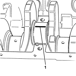
1. Fit the calibrated wire (plastigage) for measuring the bearing clearance.
Check one journal at a time, without rotating the crankshaft.
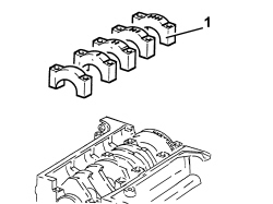
1. Fit the main bearing caps complete with half-bearings.
The bearing caps have progressively numbered references (from zero to four starting from the front of the engine) which define the fitting position.
1. Tighten the bearing cap bolts (1a) to the recommended torque using the angular tightening tool (1b).
| Component | Fastening | dia | Value (daNm) | Validity |
|---|---|---|---|---|
| Bearing caps | Bolt | M12 | 2.4 ÷ 2.6 + 100° | 1.9 Multijet |
| Tool | Description | Function | Validity |
|---|---|---|---|
| 1860942000 | Torque wrench | Tighten bolts to torque plus angle |
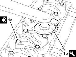
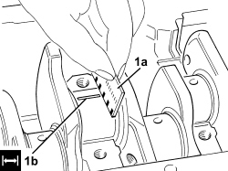
1. Remove the bearing caps fitted previously and, using a suitable graduated measuring instrument (1a), measure the clearance shown by the calibrated wire (1b).
| Measurement | Value | Validity |
|---|---|---|
| Clearance between main bearings - crankshaft main journals (mm) | 0.011 ÷ 0.071 | 1.9 Multijet |
If the figure measured is outside of the tolerance, replace the half-bearings with ones of the correct size and category.
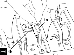
- Measure the clearance for all the bearings taking care to take the measurements one at a time without moving the crankshaft at any time.
- Check that the small end bush internal diameter is within the recommended limits; if not, replace the worn small end bush.
Op. 1028H58 CONNECTING ROD SMALL END BUSH (ONE) - REPLACE
| Measurement | Value | Validity |
|---|---|---|
| Small end bush inner diameter (mm) | 26.006 ÷ 26.012 | 1.9 Multijet |
- Check that the diameter of the gudgeon pin housing corresponds to the recommended figures; if not, replace the piston complete with piston rings, gudgeon pin and bushes.
| Measurement | Value | Validity |
|---|---|---|
| Gudgeon pin housing diameter in pistons (mm) | 25.999 ÷ 26.004 | 1.9 Multijet |
- Check that the outer diameter of the piston pins is within the recommended limits; if not, replace the worn piston pins.
| Measurement | Value | Validity |
|---|---|---|
| Piston pin outer diameter (mm) | 25.982 ÷ 25.987 | 1.9 Multijet |
- Fit the piston rings in the cylinder bore and check that the opening between the ends is within the recommended values; if this is not the case, replace the circlips.
| Measurement | Value | Validity |
|---|---|---|
| Cylinder compression 1st piston ring gap (mm) | 0.20 ÷ 0.35 | 1.9 Multijet |
| Measurement | Value | Validity |
|---|---|---|
| Cylinder compression 2nd piston ring gap (mm) | 0.25 ÷ 0.50 | 1.9 Multijet |
| Measurement | Value | Validity |
|---|---|---|
| Piston oil scraper ring gap (mm) | 0.25 ÷ 0.50 | 1.3 Multijet 1.9 Multijet |
- Check that the piston ring seat is within the recommended values.
| Measurement | Value | Validity |
|---|---|---|
| Piston ring seat in piston - 1st groove (mm) | 2.080 ÷ 2.100 | 1.9 Multijet |
| Measurement | Value | Validity |
|---|---|---|
| Piston ring seat in piston - 2nd groove (mm) | 2.020 ÷ 2.040 | 1.9 Multijet |
| Measurement | Value | Validity |
|---|---|---|
| Piston ring seat in piston - 3rd groove (mm) | 2.020 ÷ 2.040 | 1.9 Multijet |
- Check that the thickness of the piston rings is within the recommended limits.
| Measurement | Value | Validity |
|---|---|---|
| Cylinder compression 1st piston ring thickness (mm) | 1.970 ÷ 1.995 | 1.3 Multijet 1.9 Multijet |
| Measurement | Value | Validity |
|---|---|---|
| Cylinder compression 2nd piston ring thickness (mm) | 1.970 ÷ 1.995 | 1.9 Multijet |
| Measurement | Value | Validity |
|---|---|---|
| Piston oil scraper ring size (mm) | 1.970 ÷ 1.990 | 1.3 Multijet 1.9 Multijet |
- Check that the outer diameter of the pistons corresponds to the recommended figures; if not, replace the piston complete with piston rings and gudgeon pin.
| Measurement | Value | Validity |
|---|---|---|
| Piston outer diameter -Grade A (mm) | 81.920 ÷ 81.930 | 1.9 Multijet |
| Measurement | Value | Validity |
|---|---|---|
| Piston outer diameter - Grade B (mm) | 81.930 ÷ 81.940 | 1.9 Multijet |
| Measurement | Value | Validity |
|---|---|---|
| Piston outer diameter - Grade C (mm) | 81.940 ÷ 81.950 | 1.9 Multijet |
Measure perpendicular to the gudgeon pin axis, 8 mm from the lower edge of the skirt.
- Check that the axial clearance between the pistons rings and the seats corresponds to the recommeded figures.
| Measurement | Value | Validity |
|---|---|---|
| Cylinder compression 1st piston ring endfloat (mm) | 0.0085 ÷ 0.130 | 1.9 Multijet |
| Measurement | Value | Validity |
|---|---|---|
| Cylinder compression 2nd piston ring endfloat (mm) | 0.025 ÷ 0.070 | 1.9 Multijet |
| Measurement | Value | Validity |
|---|---|---|
| Oil scraper ring endfloat (mm) | 0.030 ÷ 0.070 | 1.3 Multijet 1.9 Multijet |
1. Fit the caps (1b) on the connecting rods (1a) and secure them tightening the bolts (1c) to the recommended torque.
| Component | Fastening | dia | Value (daNm) | Validity |
|---|---|---|---|---|
| Connecting rod big end bearing caps | Bolt | M9 | 2.4 ÷ 2.6 + 60° | 1.9 Multijet |
- Use the tool for the angular tightening of the connecting rod cap bolts.
| Tool | Description | Function | Validity |
|---|---|---|---|
| 1860942000 | Torque wrench | Tighten bolts to torque plus angle |
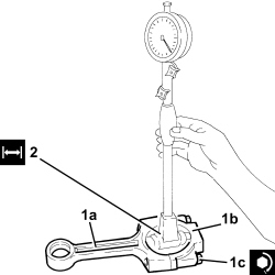
2. - Check that the diameter of the big end corresponds to the recommended figures; if not, replace the connecting rods.
| Measurement | Value | Validity |
|---|---|---|
| Big end diameter (mm) | 53.897 ÷ 53.909 | 1.9 Multijet |
Op. 1084B18 ENGINE OIL PUMP, REMOVED - CHECK AT BENCH
- Fit the intake duct on the oil pump and secure it using the bolts.
- Fit the crankcase on the overhaul stand and secure it using the bolts.
- Position the rpm sensor in its housing and secure it using the bolt.
- Place the jets in their housings in the crankcase and secure them using the bolts.
- Place the thrust washers in their seats on the third main bearing.
- The main journal half-bearings fitted on the crankshaft have been selected for their optimum fitting clearance.
The crankshaft supplied by the Parts Dept. comes without half-bearings and the main journals and crankpins are the "normal" size; the half-bearings to be fitted must therefore be selected identifying the class of each main journal and crankpin for the new crankshaft.
The following must be determined for the selection of main journal half-bearings:
- the numerical code stamped on the flywheel;
- the paint mark, if present, next to the main journals.
Below is an example of the identification of main journal grades.
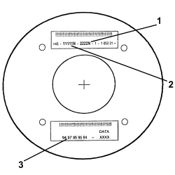
1 - Crankpin identification numerical code: the left number refers to the first timing side bearing; the final "N" is an insignificant code for 4 cylinder engines.
2 - Main journal identification numerical code: the first number refers to the first timing side bearing; the final "N" is an insignificant code for 4 cylinder engines.
3 - Series of numbers (if present), in groups of two digits, which indicate the dimensions (thousandth part) of the main journals: the first two numbers on the left refer to the first timing side bearing.
Only use the codes that relate to the key, all other codes on the flywheel should not be used.
- For the identification of the main journal grade, refer to the numerical code for reference 2 in the key.
- In the case of the example, the numbers 11111N indicate that all five bearings are Grade A (red) as indicated below.
- A further method for identifying the grade of the bearings is to read reference 3 (if present) in the diagram.
In the case of the example, the number 94 (first on the left) corresponds to the dimensions 52.994 for the first timing side bearing which identifies Grade A (red); the same method should be applied for other groups of two digits for the same reference 3 (97 - 95 - 95 - 94).
MAIN JOURNAL IDENTIFICATION
- Main journal grade A (normal), diameter 59.994 - 60.000 mm, RED paint mark, numerical code 1 (94 00)*
- Main journal grade B (normal), diameter 59.987 - 59.993 mm, BLUE paint mark, numerical code 2 (87 93)*
- Main journal grade C (normal), diameter 59.982 - 59.986 mm, YELLOW paint mark, numerical code 3 (82 86)*
- Main journal grade D (0.127 mm undersize), diameter 59.867 - 59.873 mm, BROWN paint mark, numerical code 6 (67 73)*
- Main journal grade E (0.127 mm undersize), diameter 59.860 - 59.866 mm, GREEN paint mark, numerical code 7 (60 66)*
- Main journal grade F (0.127 mm undersize), diameter 59.855 - 59.859 mm, BLACK paint mark, numerical code 8 (55 59)*
- (*): Last two numbers (thousandth part) of the main journal dimensions.
- In the case of the usage of a crankshaft where the maximum undersize for the bearings is 0.127 mm through grindings, the grade should be selected through the measurement of the diameter of the bearing using the above as a reference.
- Having defined the grade and the colour of each new or reground crankshaft bearings, it is necessary to select the thickness of the bearings that should be the same colour as the corresponding bearing; the pair of half-bearings required can be ordered from the Parts Dept. by quoting the order no.
- The above is designed to guarantee the optimum operational clearances for all the bearings.
Lastly, we wish to point out that, generally, the clearance between the main journal and the half-bearing, obtained through the selection method indicated above, should be within the following values:
- Minimum: 0.025 mm - Maximum: 0.052 mm; this value can be measured, as a final check, using the calibrated wire (Plastigage).
- Place the bearing caps complete with half-bearings in their seats.
The bearing caps have progressively numbered references (from zero to four starting from the front of the engine) which define the fitting position.
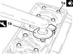
1. Tighten the bearing cap bolts (1a) to the recommended torque using the angular tightening tool (1b).
| Component | Fastening | dia | Value (daNm) | Validity |
|---|---|---|---|---|
| Bearing caps | Bolt | M12 | 2.4 ÷ 2.6 + 100° | 1.9 Multijet |
| Tool | Description | Function | Validity |
|---|---|---|---|
| 1860942000 | Torque wrench | Tighten bolts to torque plus angle |
- Fit the tool.
| Tool | Description | Function | Validity |
|---|---|---|---|
| 1860815000 | Flange | Crankshaft rotation | 1.9 Multijet |
- Rotate the crankcase through 90° on the overhaul stand.
- Rotate the crankshaft using the tool fitted previously until the cylinder concerned is at B.D.C.
- Refit the piston-connecting rod assemblies (1a) in their seats with upper connecting rod bearing halves using tool (1b).
For the selection of the connecting rod half-bearings, follow the procedure described previously for the main journal half-bearings.
The piston-connecting rod assemblies are fitted in the cylinder block/crankcase so that the combustion chamber in the piston is facing the intake side.
1. Test the crankpin clearance by applying plastigage to measure crankpin installation clearance.
- Place the crank pin caps complete with half-bearings in their seats.
Fit the connecting rods so that the number stamped on each rod faces toward the same side as the number stamped on the big end (inlet side).
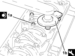
1. Tighten the bolts (1a) to torque, using the angular tightening tool (1b).
| Component | Fastening | dia | Value (daNm) | Validity |
|---|---|---|---|---|
| Connecting rod big end bearing caps | Bolt | M9 | 2.4 ÷ 2.6 + 60° | 1.9 Multijet |
| Tool | Description | Function | Validity |
|---|---|---|---|
| 1860942000 | Torque wrench | Tighten bolts to torque plus angle |
- Undo the nuts and remove the bearing caps tightened previously.
- Check that the thickness of the connecting rod half-bearings is within the recommended limits.
| Measurement | Value | Validity |
|---|---|---|
| Crankpin half-bearings - Category A (red) (mm) | 1.527 ÷ 1.531 | 1.9 Multijet |
| Measurement | Value | Validity |
|---|---|---|
| Crankpin half-bearings - Category B (light blue) (mm) | 1.530 ÷ 1.534 | 1.9 Multijet |
| Measurement | Value | Validity |
|---|---|---|
| Crankpin half-bearings - Category C (yellow) (mm) | 1.533 ÷ 1.537 | 1.9 Multijet |
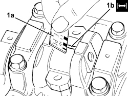
1. Use an appropriate graduated measuring tool (1a) to measure the clearance indicated by the plastigage (1b).
| Measurement | Value | Validity |
|---|---|---|
| Clearance between connectring rod bearings - crankpins (mm) | 0.030 ÷ 0.056 | 1.9 Multijet |
- If the value measured is not within the recommended figures, replace the connecting rod bearings.
- Carry out this test on all the crankpins, one at a time, without ever turning the crankshaft.
- Fit the connecting rod cap complete with half-bearing and secure it without tightening the bolts.
Fit the connecting rods so that the number stamped on each rod faces toward the same side as the number stamped on the big end (inlet side).
- Tighten the connecting rod cap bolts to the recommended torque using the angular tightening tool.
| Component | Fastening | dia | Value (daNm) | Validity |
|---|---|---|---|---|
| Connecting rod big end bearing caps | Bolt | M9 | 2.4 ÷ 2.6 + 60° | 1.9 Multijet |
| Tool | Description | Function | Validity |
|---|---|---|---|
| 1860942000 | Torque wrench | Tighten bolts to torque plus angle |
- Remove the tool.
| Tool | Description | Function | Validity |
|---|---|---|---|
| 1860815000 | Flange | Crankshaft rotation | 1.9 Multijet |
- Place the crankcase rear cover with built in oil seal in its housing.
- Tighten the crankcase rear cover bolts to the recommended torque.
| Component | Fastening | dia | Value (daNm) | Validity |
|---|---|---|---|---|
| Crankshaft to crankcase rear cover | Bolt (to be replaced) | M6 | 0.8 ÷ 1.0 | 1.9 Multijet |
- Undo the cover and replace the oil filter cartridge.
- Place the engine oil filter mounting complete with heat exchanger in position and secure it tightening the bolts to the recommended torque.
| Component | Fastening | dia | Value (daNm) | Validity |
|---|---|---|---|---|
| Water/engine oil heat exchanger support | Bolt | M10 | 4.5 ÷ 5.5 | 1.9 Multijet |
- Fit the front crankcase cover with built-in oil pump complete with intake chamber and secure by tightening bolts to the specified torque.
| Component | Fastening | dia | Value (daNm) | Validity |
|---|---|---|---|---|
| Crankshaft oil seal front cover | Bolt (to be replaced) | M6 x 1 x 22 | 0.8 ÷ 1.0 | 1.9 Multijet |
| Component | Fastening | dia | Value (daNm) | Validity |
|---|---|---|---|---|
| Crankshaft oil seal front cover | Bolt | M6 x 1 x 35 | 0.8 ÷ 1.0 | 1.9 Multijet |
- Place the seal in its housing on the oil pump using the tool.
| Tool | Description | Function | Validity |
|---|---|---|---|
| 1860816000 | Fitting tool | Fitting oil pump seal | 1.9 Multijet |
- Position the toothed timing drive pulley in its housing and tighten the bolt (left hand thread) to the recommended torque.
| Component | Fastening | dia | Value (daNm) | Validity |
|---|---|---|---|---|
| Toothed drive pulley | Left hand bolt | M16 | 32.3 ÷ 35.7 | 1.9 Multijet |
- Place the mounting complete with timing belt moving tensioner back in its housing and tighten the bolts to the recommended torque.
| Component | Fastening | dia | Value (daNm) | Validity |
|---|---|---|---|---|
| Timing tensioner moving support | Bolt | M12 | 2.8 ÷ 3.1 + 40° +/- 2° | 1.9 Multijet |
- Clean the residues of sealant from the mating surfaces between the engine block and the crankcase sump.
- Apply a strip of silicone sealant to the contact surfaces between the crankcase sump and the engine block.
The sealant strip must be unbroken.
- Place the oil sump back in its housing.
When fitting the crankcase sump, take care not to damage the sealant strip.
Finish the installation operation within 10 minutes of applying the sealant.
- Tighten the side bolts fixing the crankcase sump.
| Component | Fastening | dia | Value (daNm) | Validity |
|---|---|---|---|---|
| Engine oil sump | Side bolts | M8 | 2.2 ÷ 2.7 | 1.9 Multijet |
- Tighten the bolts securing the sump to the crankcase, camshaft side and gearbox side, to the specified torque with the tool.
| Component | Fastening | dia | Value (daNm) | Validity |
|---|---|---|---|---|
| Engine oil sump | Timing side and gearbox side bolts | M6 | 0.8 ÷ 1.0 | 1.9 Multijet |
| Tool | Description | Function | Validity |
|---|---|---|---|
| 1860833000 | Spanner | Loosen/ tighten the bolts securing the crankcase sump, timing side and gearbox side | 1.9 Multijet |
- Rotate the engine through 180° on the overhaul stand.
- Place the air conditioning compressor complee with mounting back in its housing and tighten the bolts to the recommended torque.
| Component | Fastening | dia | Value (daNm) | Validity |
|---|---|---|---|---|
| Compressor support | Bolt | M10x1.25x85 | 4.5 ÷ 5.5 | 1.9 Multijet |
1. Measure the piston projection in two places at 180° on the gudgeon pin axis using the tool and take the average of the two values measured for each piston.
| Tool | Description | Function | Validity |
|---|---|---|---|
| 1820253000 | Dial gauge support | Measure the piston projection/valve recess in relation to the cylinder head plane | 1.9 Multijet |
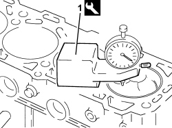
- Select the correct size cylinder head gasket depending on the maximum value between of the averages of the projection for each individual piston.
| Measurement | Value | Validity |
|---|---|---|
| Cylinder head gasket size with average maximum piston projection (mm) | projection 0.014 ÷ 0.104 thickness (no reference) 0.770 ÷ 0.870 | 1.9 Multijet |
| Measurement | Value | Validity |
|---|---|---|
| Cylinder head gasket size with average maximum piston projection (mm) | projection 0.105 ÷ 0.205 thickness (one reference) 0.870 ÷ 0.970 | 1.9 Multijet |
| Measurement | Value | Validity |
|---|---|---|
| Cylinder head gasket size with average maximum piston projection (mm) | projection 0.206 ÷ 0.294 thickness (two references) 0.970 ÷ 1.070 | 1.9 Multijet |
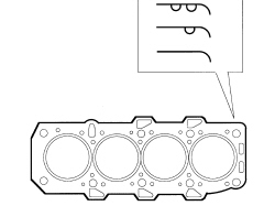
- Place the cylinder head centering bushes on the cylinder block.
- Place the cylinder head gasket selected in position.
The cylinder head gasket is ASTADUR type. The material from which the gasket is made undergoes a polymerization process during the operation of the engine so that it becomes considerably harder during usage. In order for the polymerization process to take place, it is necessary to:
- keep the gasket sealed in its casing until it is fitted;
- not lubricate the gasket or the contact surfaces with oil.
- Position the cylinder head on the cylinder block/crankcase.
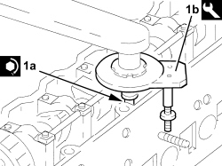
1. Tighten the cylinder head bolts (1a) to the recommended torque using the angular tightening tool (1b).
| Component | Fastening | dia | Value (daNm) | Validity |
|---|---|---|---|---|
| Cylinder head | Bolt | M12 | 6.5 + 90° + 90° + 90° | 1.9 Multijet |
| Tool | Description | Function | Validity |
|---|---|---|---|
| 1860942000 | Torque wrench | Tighten bolts to torque plus angle |
Achieve the figure of 6.5 daNm by a pretightening of 2.0 daNm subsequently increased by a torque of 4.5 daNm to achieve a nominal value of 6.5 daNm
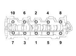
Follow the order shown in the figure for each tightening sequence.
- Place the tappet cover complete with gasket back in its housing and secure it by tightening the bolts to the recommended torque.
| Component | Fastening | dia | Value (daNm) | Validity |
|---|---|---|---|---|
| Tappet cover | Bolt | M6 | 0.8 ÷ 1.0 | 1.2 8v 1.4 8v 1.3 Multijet 1.9 Multijet |
- Place the pressure pump mounting complete with alternator back in its housing and tighten the bolts to the recommended torque.
| Component | Fastening | dia | Value (daNm) | Validity |
|---|---|---|---|---|
| Pressure pump mounting | Bolt (to be replaced) | M8 | 2.3 ÷ 2.8 | 1.9 Multijet |
- Place the pipe from the pressure pump to the fuel return manifold pipe back in its housing and secure it using the bands.
- Place the new rigid pipe between the pump and the fuel manifold back in its housing and secure it tightening the connectors to the recommended torque.
| Component | Fastening | dia | Value (daNm) | Validity |
|---|---|---|---|---|
| Pipe from pressure pump to fuel manifold - fuel manifold side | Connector | M14 | 2.2 ÷ 2.4 | 1.9 Multijet |
| Component | Fastening | dia | Value (daNm) | Validity |
|---|---|---|---|---|
| Pipe from pressure pump to fuel manifold - pressure pump side | Connector | M12 | 2.2 ÷ 2.4 | 1.9 Multijet |
1. Undo the bolt fixing the crankcase front cover shown in the diagram.
- Temporarily fit the toothed timing drive belt on the toothed drive pulley.
2. Fit the tool.
The crankshaft must be rotated, using small movements, to allow the locating dowel on the timing drive pulley to be inserted in the opening in the tool.
| Tool | Description | Function | Validity |
|---|---|---|---|
| 2000003000 | Template | Engine tuning | 1.9 Multijet |
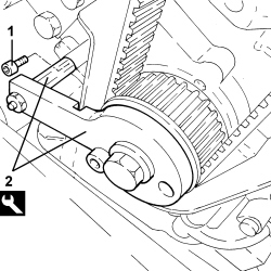
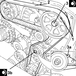
1. Rotate the driven toothed pulley until the timing references are aligned.
2. Fully fit the toothed timing drive belt.
3. Use a screwdriver for leverage on the tensioner arm until the reference (3a) for the tensioner is in the maximum tension position and tighten the tensioner bolt (3b) to the recommended torque in this position.
| Component | Fastening | dia | Value (daNm) | Validity |
|---|---|---|---|---|
| Timing moving tensioner | Nut | M8 | 2.3 ÷ 2.8 | 1.9 Multijet |
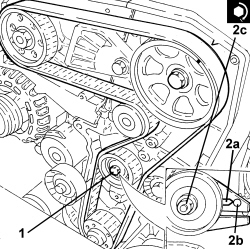
- Remove the timing tool.
- Rotate the crankshaft through two revolutions.
1. Loosen the moving timing tensioner nut.
2. Use a screwdriver for leverage on the tensioner arm until the reference (2a) for the tensioner is in line with the reference opening (2b) and tighten the tensioner bolt (2c) to the recommended torque in this position.
| Component | Fastening | dia | Value (daNm) | Validity |
|---|---|---|---|---|
| Timing moving tensioner | Nut | M8 | 2.3 ÷ 2.8 | 1.9 Multijet |
- Rotate the crankshaft through two revolutions and check that the reference for the tensioner remains in line with the reference opening.
- Check the correct timing again, refitting the timing tools and checking the timing references are aligned.
- If not, repeat the tensioning/timing procedure.
- Tighten the bolt fixing the crankcase front cover removed previously.
- Fit the power unit rigid support and tighten the bolts to the recommended torque.
| Component | Fastening | dia | Value (daNm) | Validity |
|---|---|---|---|---|
| Timing side power unit rigid support | Bolt | M10 | 4.5 ÷ 5.5 | 1.9 Multijet |
- Position the auxiliary drivebelt fixed tensioner in its housing and secure it tightening the bolt to the recommended torque.
| Component | Fastening | dia | Value (daNm) | Validity |
|---|---|---|---|---|
| Engine components single belt fixed tensioner | Bolt | M8 | 2.2 ÷ 2.7 | 1.9 Multijet |
- Position the crankshaft pulley in its housing and tighten the bolts to the recommended torque.
| Component | Fastening | dia | Value (daNm) | Validity |
|---|---|---|---|---|
| Services pulley on crankshaft | Bolt | M8 | 2.3 ÷ 2.8 |
- Place the engine components single belt in its housing using a spanner on the moving tensioner.
- Place the exhaust manifold gasket in its housing.
- Place the exhaust manifold - turbocharger assembly complete with precatalyzer back in its housing and secure it tightening the nuts to the recommended torque.
| Component | Fastening | dia | Value (daNm) | Validity |
|---|---|---|---|---|
| Turbocharger assembly and exhaust manifold - cylinder head side | Nut | M8 | 2.2 ÷ 2.7 | 1.9 Multijet |
- Connect the engine oil return hose from the turbocharger to the crankcase and tighten the bolts to the recommended torque.
| Component | Fastening | dia | Value (daNm) | Validity |
|---|---|---|---|---|
| Engine oil return pipe from turbo - crankcase side | Bolt | M8 | 2.2 ÷ 2.7 | 1.9 Multijet |
- Connect the engine oil turbocharger supply pipe to the crankcase and tighten the bolts to the recommended torque.
| Component | Fastening | dia | Value (daNm) | Validity |
|---|---|---|---|---|
| Engine oil supply pipe to turbocharger - crankcase side | Connector | M12 | 2.2 ÷ 2.7 | 1.9 Multijet |
- Connect the E.G.R. exhaust gas intake hose to the exhaust manifold and secure it using the bolts.
- Place the oil dipstick pipe back in its housing and fasten it to the oil sump using the bolt.
- Place the water pump rigid return in position and secure it using the bolts.
- Connect the hose to the rigid pipe and securing it using the band.
- Place the timing belt side guard in its housings and secure it using the bolts.
- Fit the timing belt protective cover and secure it using the bolts.
- Place the support complete with vacuum reservoir in position, seucre it using the bolts and connect the two pipes.
- Place the duplex pipes in position and connect them to the water-oil heat exchanger.
- Connect the heater coolant supply and return pipes to the thermostat.
- Refit the electrical wiring
- Connect the electrical connection for the fuel pressure sensor.
- Connect the electrical connection for the throttle casing.
- Connect the electrical connection for the coolant temperature sensor.
- Connect the electrical connection for the excess pressure sensor.
- Connect the electrical connection for the E.G.R. solenoid valve.
- Connect the electrical connections for the injectors.
- Connect the electrical connection for the fuel pressure regulator.
- Connect the glow plug electrical connections.
- Connect the electrical connection for the engine oil level sensor.
- Connect the electrical connection for the rpm sensor.
- Connect the electrical connections for the alternator.
- Connect the electrical connection for the minimum engine oil pressure switch.
- Connect the electrical connection for the air conditioning compressor engagement solenoid.
Op. 1004D40 ENGINE - POSITION ON STAND AND REMOVE
Removing
1. Undo the bolt (1a) and remove the rpm sensor (1b).
2. Undo the bolts (2a) and remove the rigid coolant inlet pipe to the water pump (2b) complete with O-Ring (2c).
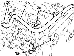
- Undo the bolts and remove the engine oil heat exchanger protection.
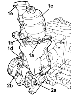
1. Undo the bolts (1a) and remove the engine oil filter mount (1b) complete with engine oil filter (1c), engine oil heat exchanger (1d) and engine oil filler fitting (1e).
- Remove the gasket.
2. Undo bolts (2a) and remove the air conditioner compressor (2b).
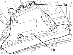
1. Undo the bolts (1a) and remove the air conditioner compressor mount (1b).
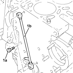
1. Undo the connectors (1a) and remove the engine pipe (1b).
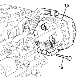
1. Undo the bolts (1a) and remove the alternator (1b).
1. Undo the bolts (1a) and remove the alternator mounting (1b).
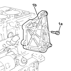
1. Undo the bolts (1a) and remove the vacuum reservoir (1b).
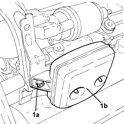
1. Undo the bolts (1a) and remove the engine oil recovery manifold (1b).
2. Undo the bolts (2a) and remove the starter motor (2b).
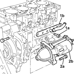
- Rotate the engine through 180° on the overhaul stand.
1. Undo the lower crankcase retaining bolts.
2. Cut the lower crankcase sealant using the tool.
| Tool | Description | Function | Validity |
|---|---|---|---|
| 1870718000 | Blade | Cut sealant |
3. Remove the lower crankcase.
- Remove the lower main journal half-bearings.
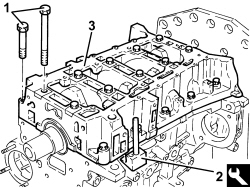
1. Undo the bolts (1a) and remove the connecting rod caps (1b).
2. Remove the lower crankpin half-bearings.
3. Remove the connecting rod - piston assemblies.
4. Remove the upper connecting rod half-bearings.
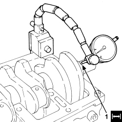
1. Check that the crankshaft endfloat corresponds to the recommended figures using a magnetic base and dial gauge.
| Measurement | Value | Validity |
|---|---|---|
| Crankshaft endfloat (mm) | 0.055 ÷ 0.265 | 1.2 8v 1.4 8v 1.3 Multijet |
- If the value for the crankshaft endfloat does not correspond with the recommended figures, when refitting, regrind the crankcase seat and use suitable oversize thrust washers.
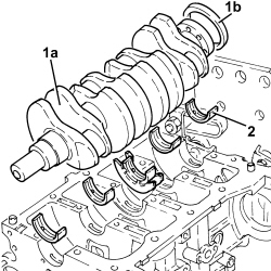
1. Remove the crankshaft (1a) complete with rear oil seal (1b).
2. Remove the upper main journal half-bearings.
The central main bearing half is joined to the thrust half-rings. Press the ends of the half-bearing to separate.
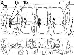
1. Undo the bolts (1a) and remove the engine oil jets (1b).
2. Remove the lower engine block locating bushes.
- Use an appropriate tool to support the upper engine block.
- Unscrew the retaining bolts and separate the upper crankcase from the overhaul stand plate.
- Position the upper crankcase on a suitable workbench.
Op. 1084B18 ENGINE OIL PUMP, REMOVED - CHECK AT BENCH
- Drill and remove the water/oil sealing plugs from the crankcase to allow for washing the ducts.
Refitting
- Clean sealant residues off the mating surfaces between: cylinder head extension/lower cylinder head, upper crankcase/lower crankcase and lower crankcase/crankcase sump.
- Clean the parts removed thoroughly and check their condition visually.
- Fit the water/oil sealing plugs in the crankcase using suitable fitting tools.
- Lubricate all the mechanical components with engine oil.
1. Measure the cylinder bore diameter using the diagram illustrated.
| Measurement | Value | Validity |
|---|---|---|
| Cylinder liner diameter - Grade A (mm) | 69.600 ÷ 69.610 | 1.3 Multijet |
| Measurement | Value | Validity |
|---|---|---|
| Cylinder liner diameter - Grade B (mm) | 69.610 ÷ 69.620 | 1.3 Multijet |
| Measurement | Value | Validity |
|---|---|---|
| Cylinder liner diameter - Grade C (mm) | 69.620 ÷ 69.630 | 1.3 Multijet |
- Check that the taper of the cylinder liners/bores is within the recommended limits.
| Measurement | Value | Validity |
|---|---|---|
| Cylinder liner taper (mm) | < 0.010 | 1.3 Multijet |
- Check that the ovality of the cylinder liners is within the recommended limits.
| Measurement | Value | Validity |
|---|---|---|
| Cylinder liner ovality (mm) | +/- 0.005 | 1.3 Multijet |
- If the cylinder bore measurements are not within the recommended limits, ream the cylinder bores following the recommended oversizes.
In the case of reaming, all the bores must have the same oversize.
| Measurement | Value | Validity |
|---|---|---|
| Cylinder liner diameter oversize (mm) | 0.1 | 1.2 8v 1.4 8v 1.4 16v 1.3 Multijet 1.9 Multijet |
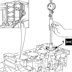
- Use an appropriate support tool to replace the upper crankcase on the overhaul stand.
- Refit the lower crankcase locating bushes in their seats.
- Provisionally fit the lower engine block on the upper engine block to measure the main journal seats and then remove it.
1. Loosen the central bolts (1a) securing the lower crankcase to the specified torque, following the order shown in the figure. Use tool (1b) for angular tightening.
| Component | Fastening | dia | Value (daNm) | Validity |
|---|---|---|---|---|
| Cylinder block/crankcase | Central bolt | M10 | 1.9 ÷ 2.1 + 80° +/- 3° | 1.3 Multijet |
| Tool | Description | Function | Validity |
|---|---|---|---|
| 1860942000 | Torque wrench | Tighten bolts to torque plus angle |
2. Tighten the lower crankcase side bolts to the specified torque, following the order shown in the figure.
| Component | Fastening | dia | Value (daNm) | Validity |
|---|---|---|---|---|
| Cylinder block/crankcase | Side bolt | M8 | 2.9 ÷ 3.2 | 1.3 Multijet |
3. Check that the diameter of the main journal seats is within specified limits (without fitting the half-bearings).
| Measurement | Value | Validity |
|---|---|---|
| Main journal seat diameter - Category A (mm) | 54.710 ÷ 54.714 | 1.3 Multijet |
| Measurement | Value | Validity |
|---|---|---|
| Main journal seat diameter - Category B (mm) | 54.714 ÷ 54.718 | 1.3 Multijet |
| Measurement | Value | Validity |
|---|---|---|
| Main journal seat diameter - Category C (mm) | 54.718 ÷ 54.722 | 1.3 Multijet |
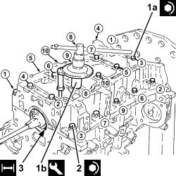
- Check that there are no deposits or blockages in the crankshaft lubrication ducts.
- Check that the diameter of the main journals corresponds to the recommended figures.
| Measurement | Value | Validity |
|---|---|---|
| Main journal diameter - Category A (mm) | 50.994 ÷ 51.000 | 1.3 Multijet |
| Measurement | Value | Validity |
|---|---|---|
| Main journal diameter - Category B (mm) | 50.988 ÷ 50.994 | 1.3 Multijet |
| Measurement | Value | Validity |
|---|---|---|
| Main journal diameter - Category C (mm) | 50.982 ÷ 50.988 | 1.3 Multijet |
- If the diameter of the main journals is not correct, they should be reground to the recommended undersize.
| Measurement | Value | Validity |
|---|---|---|
| Main journal diameter undersize (mm) | 0.127 | 1.2 8v 1.4 8v 1.4 16v 1.3 Multijet |
Crankpin undersizes higher than the value mentioned will adversely affect the structural resistance of the crankshaft (following contact between the tool and rolled connectors). As far as the above is concerned, if the regrinding requires undersizes greater than 0.127 mm, then the crankshaft must be replaced and a new one ordered from the Parts Dept. The half-bearings used for undersizes of more than 0.127 mm should not be ordered from the Parts Dept. (even if the number is still quoted).
- Check that the diameter of the crankpins corresponds to the recommended figures.
| Measurement | Value | Validity |
|---|---|---|
| Crankpin diameter - Category A (mm) | 42.591 ÷ 42.600 | 1.3 Multijet |
| Measurement | Value | Validity |
|---|---|---|
| Crankpin diameter - Category B (mm) | 42.582 ÷ 42.591 | 1.3 Multijet |
- If the diameter of the crankpins is not correct, they should be reground to the recommended undersize.
| Measurement | Value | Validity |
|---|---|---|
| Crankpin diameter undersize (mm) | 0.127 | 1.2 8v 1.4 8v 1.4 16v 1.3 Multijet 1.9 Multijet |
Crankpin undersizes higher than the value mentioned will adversely affect the structural resistance of the crankshaft (following contact between the tool and rolled connectors). As far as the above is concerned, if the regrinding requires undersizes greater than 0.127 mm, then the crankshaft must be replaced and a new one ordered from the Parts Dept. The half-bearings used for undersizes of more than 0.127 mm should not be ordered from the Parts Dept. (even if the number is still quoted).
- Check the crankshaft and connecting rod bearings bearing in mind that no adjustment operations should be carried out on the half-bearings. Replace them if scoring or signs of binding are noted.
- The size of the main journal half-bearings is given.
| Measurement | Value | Validity |
|---|---|---|
| Main journal half-bearings - Category A (red) (mm) | 1.836 ÷ 1.841 | 1.3 Multijet |
| Measurement | Value | Validity |
|---|---|---|
| Main journal half-bearings - Category B (blue) (mm) | 1.841 ÷ 1.846 | 1.3 Multijet |
| Measurement | Value | Validity |
|---|---|---|
| Main journal half-bearings - Category C (yellow) (mm) | 1.846 ÷ 1.851 | 1.3 Multijet |
| Measurement | Value | Validity |
|---|---|---|
| Main journal half-bearing thickness oversize (mm) | 0.127 | 1.3 Multijet |
- The size of the connecting rod half-bearings is given.
| Measurement | Value | Validity |
|---|---|---|
| Crankpin half-bearings - Category A (red) (mm) | 1.546 ÷ 1.552 | 1.3 Multijet |
| Measurement | Value | Validity |
|---|---|---|
| Crankpin half-bearings - Category B (blue) (mm) | 1.550 ÷ 1.556 | 1.3 Multijet |
| Measurement | Value | Validity |
|---|---|---|
| Connecting rod half-bearing thickness oversize (mm) | 0.127 | 1.3 Multijet |
- Place the upper main bearing halves in their seats taking great care over cleanliness.
Half-bearings of different categories may be fitted to the same journal to reduce the clearance. In the above case, observe the following installation requirements. Fit the thickest half-bearing to the main bearing cap and the thinnest to the crankcase.
If the crankshaft has been ground, fit new oversize half-bearings to restore the initial tolerance conditions. The thrust half-rings are built into the central main bearing half.
- The thrust half-ring thickness is given.
| Measurement | Value | Validity |
|---|---|---|
| Thrust half-washer thickness (mm) | 2.310 ÷ 2.360 | 1.3 Multijet |
The thrust half-washer undersize is 0.127 mm.
- Fit the crankshaft into its seat on the upper crankcase.
1. Fit the calibrated wire (plastigage) for measuring the bearing clearance.
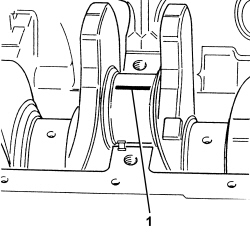
1. Refit the lower crankase with lower main bearing halves in its seat.
2. Tighten the central bolts (2a) securing the lower crankcase to the specified torque, following the order shown in the figure. Use tool (2b) for angular tightening.
| Component | Fastening | dia | Value (daNm) | Validity |
|---|---|---|---|---|
| Cylinder block/crankcase | Central bolt | M10 | 1.9 ÷ 2.1 + 80° +/- 3° | 1.3 Multijet |
| Tool | Description | Function | Validity |
|---|---|---|---|
| 1860942000 | Torque wrench | Tighten bolts to torque plus angle |
3. Tighten the lower crankcase side bolts to the specified torque, following the order shown in the figure.
| Component | Fastening | dia | Value (daNm) | Validity |
|---|---|---|---|---|
| Cylinder block/crankcase | Side bolt | M8 | 2.9 ÷ 3.2 | 1.3 Multijet |
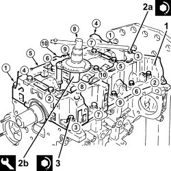
1. Remove the lower crankcase with main bearing halves fitted previously and, using a suitable graduated measuring instrument (1a), measure the clearance shown by the calibrated wire (1b).
Check one journal at a time, without rotating the crankshaft.
| Measurement | Value | Validity |
|---|---|---|
| Clearance between main bearings - crankshaft main journals (mm) | 0.028 ÷ 0.048 | 1.3 Multijet |
If the figure measured is outside of the tolerance, replace the half-bearings with ones of the correct size and category.
1. After checking all the main journals, apply a strip of specified silicon sealant to the contact surfaces between the lower crankcase and the upper crankcase as shown in the diagram in the figure.
The sealant strip must be unbroken. The sealant strip diameter must be 2.5 -3.5 mm
- After applying the sealant clean the crankshaft lower oil seal seat.
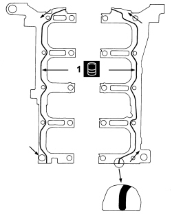
- Fit the lower crankcase to the upper crankcase permanently by tightening the bolts as shown previously.
- Check that the small end bush bore diameter is within the recommended limits; if not, replace the connecting rod assemblies.
| Measurement | Value | Validity |
|---|---|---|
| Small end bush inner diameter (mm) | 23.006 ÷ 23.012 | 1.3 Multijet |
- Check that the diameter of the gudgeon pin housing in the piston is within the recommended values.
| Measurement | Value | Validity |
|---|---|---|
| Piston pin housing diameter (mm) | 22.990 ÷ 22.996 | 1.3 Multijet 75bhp |
| Measurement | Value | Validity |
|---|---|---|
| Piston pin housing diameter (mm) | 22.991 ÷ 22.996 | 1.3 Multijet 90CV |
- If the piston pin bore diameter is not within specified values, replace the piston complete with its piston pin and rings.
- Check that the outer diameter of the piston pins is within the recommended limits; if not, replace the worn piston pins.
| Measurement | Value | Validity |
|---|---|---|
| Piston pin outer diameter (mm) | 22.982 ÷ 22.987 | 1.3 Multijet |
- Fit the piston rings in the cylinder bore and check that the opening between the ends is within the recommended values; if this is not the case, replace the circlips.
| Measurement | Value | Validity |
|---|---|---|
| Cylinder compression 1st piston ring gap (mm) | 0.20 ÷ 0.30 | 1.3 Multijet |
| Measurement | Value | Validity |
|---|---|---|
| Cylinder compression 2nd piston ring gap (mm) | 1.0 ÷ 1.5 | 1.3 Multijet |
| Measurement | Value | Validity |
|---|---|---|
| Piston oil scraper ring gap (mm) | 0.25 ÷ 0.50 | 1.3 Multijet 1.9 Multijet |
- Check that the thickness of the piston rings is within the recommended limits.
| Measurement | Value | Validity |
|---|---|---|
| Cylinder compression 1st piston ring thickness (mm) | 1.970 ÷ 1.995 | 1.3 Multijet 1.9 Multijet |
| Measurement | Value | Validity |
|---|---|---|
| Cylinder compression 2nd piston ring thickness (mm) | 1.470 ÷ 1.490 | 1.3 Multijet |
| Measurement | Value | Validity |
|---|---|---|
| Piston oil scraper ring size (mm) | 1.970 ÷ 1.990 | 1.3 Multijet 1.9 Multijet |
- Check that the thickness of the piston ring seats is within the recommended limits.
| Measurement | Value | Validity |
|---|---|---|
| Piston ring seat in piston - 1st groove (mm) | 2.08 ÷ 2.10 | 1.3 Multijet 75bhp |
| Measurement | Value | Validity |
|---|---|---|
| Piston ring seat in piston - 1st groove (mm) | 2.10 ÷ 2.12 | 1.3 Multijet 90CV |
| Measurement | Value | Validity |
|---|---|---|
| Piston ring seat in piston - 2nd groove (mm) | 1.53 ÷ 1.55 | 1.3 Multijet 75bhp |
| Measurement | Value | Validity |
|---|---|---|
| Piston ring seat in piston - 2nd groove (mm) | 1.54 ÷ 1.56 | 1.3 Multijet 90CV |
| Measurement | Value | Validity |
|---|---|---|
| Piston ring seat in piston - 3rd groove (mm) | 2.02 ÷ 2.04 | 1.3 Multijet 75bhp |
| Measurement | Value | Validity |
|---|---|---|
| Piston ring seat in piston - 3rd groove (mm) | 2.02 ÷ 2.04 | 1.3 Multijet 90CV |
- Check that the outer diameter of the pistons corresponds to the recommended figures; if not, replace the piston complete with piston rings and gudgeon pin.
| Measurement | Value | Validity |
|---|---|---|
| Piston outer diameter -Grade A (mm) | 69.520 ÷ 69.530 | 1.3 Multijet 75bhp |
| Measurement | Value | Validity |
|---|---|---|
| Piston outer diameter -Grade A (mm) | 69.546 ÷ 69.556 | 1.3 Multijet 90CV |
| Measurement | Value | Validity |
|---|---|---|
| Piston outer diameter - Grade B (mm) | 69.530 ÷ 69.540 | 1.3 Multijet 75bhp |
| Measurement | Value | Validity |
|---|---|---|
| Piston outer diameter - Grade B (mm) | 69.556 ÷ 69.566 | 1.3 Multijet 90CV |
| Measurement | Value | Validity |
|---|---|---|
| Piston outer diameter - Grade C (mm) | 69.540 ÷ 69.550 | 1.3 Multijet 75bhp |
| Measurement | Value | Validity |
|---|---|---|
| Piston outer diameter - Grade C (mm) | 69.566 ÷ 69.576 | 1.3 Multijet 90CV |
Measure perpendicular to the gudgeon pin axis, 12 mm from the lower edge of the skirt.
- Check that the axial clearance between the first ring and the housing in the piston corresponds to the recommeded figures.
| Measurement | Value | Validity |
|---|---|---|
| Cylinder compression 1st piston ring endfloat (mm) | 0.09 ÷ 0.13 | 1.3 Multijet 75bhp |
| Measurement | Value | Validity |
|---|---|---|
| Cylinder compression 1st piston ring endfloat (mm) | 0.11 ÷ 0.15 | 1.3 Multijet 90CV |
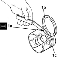
1. Check that the backlash (1a) between the second ring (1b) and the housing in the piston (1c) corresponds to the recommeded figure.
| Measurement | Value | Validity |
|---|---|---|
| Cylinder compression 2nd piston ring endfloat (mm) | 0.04 ÷ 0.08 | 1.3 Multijet 75bhp |
| Measurement | Value | Validity |
|---|---|---|
| Cylinder compression 2nd piston ring endfloat (mm) | 0.05 ÷ 0.09 | 1.3 Multijet 90CV |
- Check that the backlash between the oil scraper ring and the housing in the piston corresponds to the recommeded figures.
| Measurement | Value | Validity |
|---|---|---|
| Oil scraper ring endfloat (mm) | 0.030 ÷ 0.070 | 1.3 Multijet 1.9 Multijet |
1. Fit the caps (1b) on the connecting rods (1a) and secure them tightening the bolts (1c) to the recommended torque.
The connecting rods are pre-set fracture type and are supplied already fractured by Parts together with the cap bolts. The connecting rod caps are not interchangeable because the fracture profile differs from part to part.
| Component | Fastening | dia | Value (daNm) | Validity |
|---|---|---|---|---|
| Connecting rod big end bearing caps | Bolt | M8 | 1.9 ÷ 2.1 + 40° +/- 2° | 1.2 8v 1.4 8v 1.4 16v 1.3 Multijet |
- Use the tool for the angular tightening of the connecting rod cap bolts.
| Tool | Description | Function | Validity |
|---|---|---|---|
| 1860942000 | Torque wrench | Tighten bolts to torque plus angle |
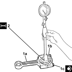
2. Check that the big end diameter (without fitting the half-bearings) is within the recommended limits; if not, replace the connecting rods.
| Measurement | Value | Validity |
|---|---|---|
| Big end diameter (mm) | 45.734 ÷ 45.744 | 1.3 Multijet |
Op. 1084B18 ENGINE OIL PUMP, REMOVED - CHECK AT BENCH
- Check that there are no signs of seizing on the flywheel ring gear teeth; if this is not the case, replace it.
- Refit the engine oil sprays in their seats and secure by tightening the bolts to the specified torque.
| Component | Fastening | dia | Value (daNm) | Validity |
|---|---|---|---|---|
| Engine oil jet | Bolt | M6 | 0.8 ÷ 1.0 | 1.3 Multijet |
The crankshaft supplied by the Parts Dept. comes without half-bearings and the main journals and crankpins are the "normal" size; the half-bearings to be fitted must therefore be selected identifying the class of each main journal and crankpin for the new crankshaft.
The letter code stamped on the timing side counter-weight is required for selecting the grade.
Below is an example of identifying the main journal and crankpin grade referring to an engine with nominal diameter main journals (51.000 mm).
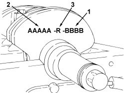
1. Crankpin alphabetical identification code - B B B B (the same for all bearings): the first letter from the left refers to the first timing side bearing.
2. Main journal alphabetical identification code - A A A A A (the same for all bearings): the first letter from the left refers to the first timing side bearing.
3. Alphabetical identification code for thrust washers - R.
Only use the alphabetical codes for references 1, 2 and 3 in the diagram, all the other codes on the counter-weight should not be used.
For the identification of the main journal grade, refer to the alphabetical code 2 shown in the diagram.
In the case of the diagram, for example, the letter code A A A A A (Grade A - Normal) indicates that all five bearings are prepared for the fitting of half-bearings with a Red coloured paint mark on the edge; as a result, specific half-bearings should be identified for different alphabetical codes (bearing grade).
Normal grades are usually used on new engines with undersizes only used in exceptional cases.
ALLOCATION OF HALF-BEARINGS TO MAIN JOURNALS
Having defined the grade for each crankshaft bearing (to which a specific diameter corresponds according to the grade), it is necessary to select the pair of bearings which are the same colour; by consulting the Parts CD-ROM it is possible to find the order no. for the pair of half-bearings required.
The above is designed to guarantee the optimum operational clearances for all the bearings.
- Main journal grade A (normal), diameter 51.000 - 50.994 mm, RED paint mark
- Main journal grade B (normal), diameter 50.994 - 50.988 mm, BLUE paint mark
- Main journal grade C (normal), diameter 50.988 - 50.982 mm, YELLOW paint mark
- Main journal grade AM (0.127 undersize), diameter 50.873 - 50.867mm, BROWN paint mark
- Main journal grade BM (0.127 undersize), diameter 50.867 - 50.861mm, GREEN paint mark
- Main journal grade CM (0.127 undersize), diameter 50.861 - 50.855mm, BLACK paint mark
Lastly, we wish to point out that, generally, the clearance between the main journal and the half-bearing, obtained through the selection method indicated above, should be within the following values:
Minimum: 0.025 mm - Maximum: 0.052 mm; this value can be measured, as a final check, using the calibrated wire (plastigage).
CLASSIFICATION OF CRANKPINS AND ALLOCATION OF HALF-BEARINGS
The procedure described for the main journal half-bearings should also be carried out for selecting the crankpin half-bearings.
- Crankpin grade A (normal), diameter 42.600 - 42.5914 mm, RED paint mark
- Crankpin grade B (normal), diameter 42.591 - 42.582 mm, BLUE paint mark
- Crankpin grade AM (0.127 undersize), diameter 42.473 - 42.464 mm, BROWN paint mark
- Crankpin grade BM (0.127 undersize), diameter 42.464 - 42.455 mm, GREEN paint mark
By way of example, if the alphabetical code identified is the one indicated by reference 1 in the diagram, i.e. - B B B B, this means that the four crankpins are all Grade B (to which a specific diameter belongs) and are therefore ready for the fitting of half-bearings with a blue coloured paint mark on the edge.
The first letter on the left - B of the alphabetical code is always related to the first timing side crankpin.
Refer to the instructions above for the pair of half-bearings to be allocated to each bearing.
The order no. for the half-bearings to be fitted which are identified by the colour can be obtained by consulting the Parts CD ROM.
CLASSIFICATION AND ALLOCATION OF THRUST WASHERS
The selection of thrust washers for the centre main journal should be made using reference 3 in the diagram (i.e. R for the normal size, RM for a 0.127 mm oversize), therefore the selection should be made using the crankshaft endfloat measured previously.
- Half-ring grade R (normal ), thickness 2.310 - 2.360 mm
- Half-ring grade RM (0.127 mm oversize), thickness 2.437 - 2.487 mm
It is advisable to keep stocks of the main journal and crankpin half-bearings currently in use in all workshop parts departments to ensure they are immediately available is required.
1. Fit the tool.
| Tool | Description | Function | Validity |
|---|---|---|---|
| 1860815000 | Flange | Crankshaft rotation | 1.4 16v 1.3 Multijet |
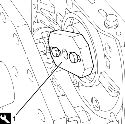
- Turn the crankshaft using the tool fitted previously.
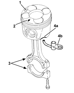
- Fit the connecting rod-piston assemblies and align in accordance with the following references.
1. Piston grade code that may be: A - B - C or AM - BM - CM for oversize pistons
2. The arrow shows the timing side.
3. Area where the number of the matching cylinder liner is stamped.
4. Exhaust (4a) on the piston skirt which should be aligned with the oil jet (4b).
1. Refit the piston-connecting rod assemblies (1a) in their seats with upper connecting rod bearing halves using tool (1b).
The connecting rod bearing halves may be identified as follows:
- upper connecting rod bearing half, connecting rod side, trimetallic and dark in colour;
- lower connecting rod bearing half, cap side bimetallic, light coloured with a hole.
Never reverse the positioning of the connecting rod bearing halves under any circumstances.
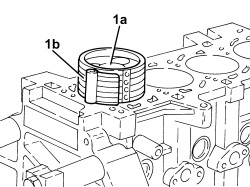
- Rotate the engine through 180° on the overhaul stand.
1. Fit the calibrated wire (plastigage) for measuring the bearing clearance.
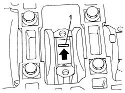
1. Refit the connecting rod cap assemblies (1a) in their seats with upper connecting rod bearing halves using tool (1b).
The connecting rod bearing halves may be identified as follows:
- upper connecting rod bearing half, connecting rod side, trimetallic and dark in colour;
- lower connecting rod bearing half, cap side bimetallic, light coloured with a hole.
Never reverse the positioning of the connecting rod bearing halves under any circumstances.
2. Tighten the connecting rod cap bolts (2a) to the recommended torque using the angular tightening tool (2b).
| Component | Fastening | dia | Value (daNm) | Validity |
|---|---|---|---|---|
| Connecting rod big end bearing caps | Bolt | M8 | 1.9 ÷ 2.1 + 40° +/- 2° | 1.2 8v 1.4 8v 1.4 16v 1.3 Multijet |
| Tool | Description | Function | Validity |
|---|---|---|---|
| 1860942000 | Torque wrench | Tighten bolts to torque plus angle |
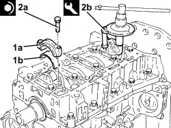
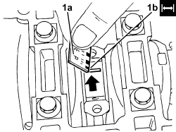
- Undo the bolts and remove the connecting rod caps with the half-bearings fitted previously.
1. Use an appropriate graduated measuring tool (1a) to measure the clearance indicated by the plastigage (1b).
Check one journal at a time, without rotating the crankshaft.
| Measurement | Value | Validity |
|---|---|---|
| Clearance between connectring rod bearings - crankpins (mm) | 0.030 ÷ 0.062 | 1.3 Multijet |
If the figure measured is outside of the tolerance, replace the connecting rod half-bearings with ones of the correct size and category.
- Fit the connecting rod caps permanently by tightening the bolts as shown previously.
- Remove the tool.
| Tool | Description | Function | Validity |
|---|---|---|---|
| 1860815000 | Flange | Crankshaft rotation | 1.4 16v 1.3 Multijet |
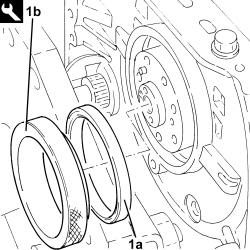
1. Fit the crankshaft rear oil seal (1a) using the tool (1b).
| Tool | Description | Function | Validity |
|---|---|---|---|
| 1870900200 | Fitting tool | Fitting crankshaft rear oil seal | 1.3 Multijet |
- Rotate the engine through 180° on the overhaul stand.
- Place the starter motor in its housing and secure it tightening the bolts to the recommended torque.
| Component | Fastening | dia | Value (daNm) | Validity |
|---|---|---|---|---|
| Starter motor | Bolt | M8 | 2.25 ÷ 2.75 |
- Place the separator condensed oil manifold in its housing and secure it by tightening the bolts to the recommended torque.
| Component | Fastening | dia | Value (daNm) | Validity |
|---|---|---|---|---|
| Engine oil recovery manifold | Bolt | M6 | 0.8 ÷ 1.0 | 1.3 Multijet |
- Place the vacuum reservoir back in its housing and secure it using the bolt.
- Place the alternator mounting in its housing and secure it tightening the bolts to the recommended torque.
| Component | Fastening | dia | Value (daNm) | Validity |
|---|---|---|---|---|
| Alternator mounting | Bolt | M8x1.25x45 | 2.0 ÷ 2.2 | 1.3 Multijet |
- Place the alternator in position and secure it tightening the bolts to the recommended torque.
| Component | Fastening | dia | Value (daNm) | Validity |
|---|---|---|---|---|
| Alternator | Bolt | M8x1.25x85 | 2.0 ÷ 2.2 | 1.3 Multijet |
- Refit the engine oil pipe in its seat on the crankcase and secure with connectors.
- Place the air conditioner compressor mounting in its housing and secure it tightening the bolts to the recommended torque.
| Component | Fastening | dia | Value (daNm) | Validity |
|---|---|---|---|---|
| Compressor support | Bolt | M8x1.25x35 | 2.0 ÷ 2.4 | 1.3 Multijet |
- Place the air conditioning compressor in its housing and secure it tightening the bolts to the recommended torque.
| Component | Fastening | dia | Value (daNm) | Validity |
|---|---|---|---|---|
| Compressor | Bolt | M8x1.25x80 | 2.0 ÷ 2.4 | 1.3 Multijet |
- Replace the engine oil filter mounting complete with the engine oil filter and engine oil filler fitting and secure by tightening the bolts to the specified torque.
Ensure the gasket is present, undamaged and correctly positioned.
| Component | Fastening | dia | Value (daNm) | Validity |
|---|---|---|---|---|
| Engine oil filter mounting | Bolt | M6 | 0.8 ÷ 1.0 | 1.3 Multijet |
- Place the water pump rigid inlet pipe, complete with O-ring in position and secure it using the bolts.
Fit the rigid pipe in the crankcase very carefuly to ensure the o-ring is correctly positioned.
- Place the rpm sensor in its housing and secure it by tightening the bolt to the recommended torque.
| Component | Fastening | dia | Value (daNm) | Validity |
|---|---|---|---|---|
| Rpm sensor | Bolt | M6 | 0.8 ÷ 1.0 | 1.3 Multijet 1.9 Multijet |
- Fit the engine oil heat exchanger protection.
1. Measure the piston projection in two places at 180° on the gudgeon pin axis using the tool and take the average of the two values measured for each piston.
| Tool | Description | Function | Validity |
|---|---|---|---|
| 1870404001 | Dial gauge support | Piston projection from cylinder head support plane check | 1.3 Multijet |
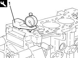
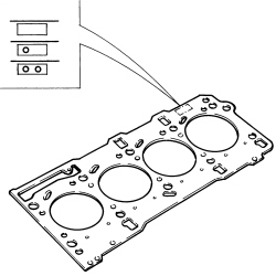
- Select the correct size cylinder head gasket depending on the maximum value between of the averages of the projection for each individual piston.
| Measurement | Value | Validity |
|---|---|---|
| Cylinder head gasket size with average maximum piston projection (mm) | projection 0.028 ÷ 0.127 thickness (no opening) 0.67 ÷ 0.77 | 1.3 Multijet |
| Measurement | Value | Validity |
|---|---|---|
| Cylinder head gasket size with average maximum piston projection (mm) | projection 0.128 ÷ 0.227 thickness (one opening) 0.77 ÷ 0.87 | 1.3 Multijet |
| Measurement | Value | Validity |
|---|---|---|
| Cylinder head gasket size with average maximum piston projection (mm) | projection 0.228 ÷ 0.327 thickness (two openings) 0.87 ÷ 0.97 | 1.3 Multijet |
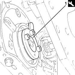
1. Fit the camshaft timing adjustment tool.
| Tool | Description | Function | Validity |
|---|---|---|---|
| 1870900300 | Template | Crankshaft tuning | 1.3 Multijet |
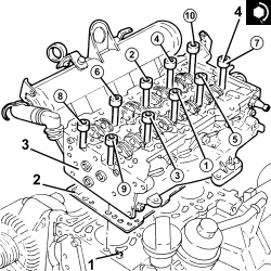
1. Fit the lower cylinder head centering bushes on the engine block.
Before fitting the centering bushes, check that the height is 10 mm.
2. Fit the new cylinder head gasket selected.
3. Position the cylinder head on the cylinder block/crankcase.
4. Tighten the cylinder head bolts to the recommended torque using the angular tightening tool.
Follow the order shown in the figure for each tightening sequence. The nominal tightening of 4.0 daNm is performed in two stages: a pretightening to 2.0 daNm followed by an additional tightening of 2.0 daNm.
There is a tolerance of 3° more or less for the two angular tightenings.
| Component | Fastening | dia | Value (daNm) | Validity |
|---|---|---|---|---|
| Cylinder head | Bolt | M10 | 3.8 ÷ 4.2 + 90° + 90° | 1.3 Multijet |
| Tool | Description | Function | Validity |
|---|---|---|---|
| 1860942000 | Torque wrench | Tighten bolts to torque plus angle |
- Check the cylinder head - crankcase misalignment.
It is only possible for the cylinder head to protrude from the crankcase.
| Measurement | Value | Validity |
|---|---|---|
| Cylinder head - crankcase misalignment (mm) | 0.1 | 1.3 Multijet |
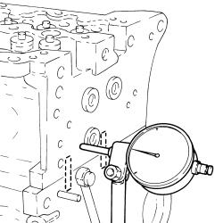
- Connect the condensed engine oil recovery pipe, oil vapour separator side, and tighten the collar.
- Tighten the bolt securing the water/exhaust gas heat exchanger for the EGR to the crankcase.
- Connect the coolant supply pipe to the engine oil heat exchanger and secure it using the band and the bolts.
Fold over the gasket safety tabs.
- Connect the E.G.R. pipe to the thermostat and secure it using the band.
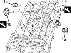
1. If not already carried out during cylinder head overhaul, remove plugs (1a) and fit camshaft timing adjustment tools (1b) to the cylinder head extension.
Fit the tools and position with their millings horizontal. Ensure they fit into the seats on the camshafts.
| Tool | Description | Function | Validity |
|---|---|---|---|
| 1870896900 | Templates | Engine tuning | 1.3 Multijet |
- Remove the intake camshaft timing tool and tighten the plug.
- Place the camshaft housing centering bushes on the cylinder head.
Before fitting the centering bushes, check that the height is 13 mm.
- Place the camshaft housing complete with gasket in position.
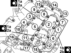
1. Tighten the single cylinder head extension bolt M8 (1a) to a pretorque of 1.5 daNm and M7 (1b) to a pretorque of 1.2 daNm
2. Tighten bolts (2a) and (2b) securing the single cylinder head extension to the specified torque.
Follow the order shown in the figure for each tightening sequence.
| Component | Fastening | dia | Value (daNm) | Validity |
|---|---|---|---|---|
| Engine camshaft housing | Bolt | M8 | 2.5 | 1.3 Multijet |
| Component | Fastening | dia | Value (daNm) | Validity |
|---|---|---|---|---|
| Engine camshaft housing | Bolt | M7 | 1.8 | 1.3 Multijet |
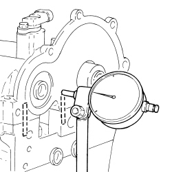
- Check the misalignment between the camshaft housing - cylinder head.
It is only possible for the cylinder head extension to protrude from the cylinder head.
| Measurement | Value | Validity |
|---|---|---|
| Misalignment between cylinder head extension - cylinder head (mm) | 0.1 | 1.3 Multijet |
- Refit new injector dust rings into their seats on the cylinder head extension.
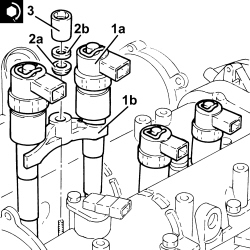
1. Refit injectors (1a) with brackets (1b) into their seats.
Before refitting, replace the copper ring on the injectors.
2. Refit the tapered washer (2a) and washer (2b) in their seats.
3. Tighten the nut securing the injector bracket to the specified torque.
| Component | Fastening | dia | Value (daNm) | Validity |
|---|---|---|---|---|
| Injector brackets | Nut | M8 | 1.8 ÷ 2.2 | 1.3 Multijet |
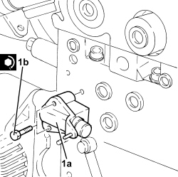
- Use a suitable tool (e.g. vice) to set the chain tensioner and hold it fully back with a retaining pin.
1. Place the chain tensioner (1a) in its housing and secure it tightening the bolts (1b) to the recommended torque.
| Component | Fastening | dia | Value (daNm) | Validity |
|---|---|---|---|---|
| Timing moving tensioner | Bolt | M6 | 0.8 ÷ 1.0 | 1.3 Multijet |
- Refit the exhaust side camshaft toothed drive pulley together with chain and toothed drive pulley.
Fit the exhaust side camshaft toothed drive pulley and the toothed drive pulley according to the position marked on disassembly. If the pulleys are replaced, fit with the wording facing outwards.
- Place the timing chain mobile pad back in its housing and secure it using the pin.
- Place the timing chain fixed pad back in its housing and secure it using the bolts.
- Tighten the bolt fixing the exhaust side camshaft toothed pulley to the recommended torque.
| Component | Fastening | dia | Value (daNm) | Validity |
|---|---|---|---|---|
| Driven toothed pulley | Bolt | M12 | 13.5 ÷ 16.5 | 1.3 Multijet |
- Remove the chain tensioner retaining pin and check that the piston is in contact with the mobile pad.
- Refit the support bracket complete with single fuel manifold pipe, fuel pressure regulator, fuel pressure sensor and secure using the bolts.
- Connect the fuel return pipe to the single fuel manifold and tighten the band.
- Fit new pipes from the fuel manifold to the injectors and secure with connectors without tightening.
- Tighten the connectors for the pipes from the fuel manifold to the injector side injectors to the recommended torque using an appropriate commercial wrench.
| Component | Fastening | dia | Value (daNm) | Validity |
|---|---|---|---|---|
| Pipes from fuel manifold to injectors - injectors side | Connector | M12 | 2.3 ÷ 2.5 | 1.3 Multijet |
- Tighten the connectors for the pipes from the fuel manifold to the fuel manifold side injectors to the recommended torque using an appropriate commercial wrench.
| Component | Fastening | dia | Value (daNm) | Validity |
|---|---|---|---|---|
| Pipes from fuel manifold to injectors - fuel manifold side | Connector | M14 | 2.6 ÷ 2.9 | 1.3 Multijet |
Clean the threaded pipe seats on the manifold and injectors with heptane.
- Place a new pipe from the pressure pump to the single fuel manifold in its housing and secure it using the connectors without tightening them.
- Tighten the connector for the pipe from the pressure pump to the single fuel manifold, pump side, to the recommended torque using a spanner.
| Component | Fastening | dia | Value (daNm) | Validity |
|---|---|---|---|---|
| Pipe from pressure pump to fuel manifold - pressure pump side | Connector | M12 | 2.3 ÷ 2.5 | 1.3 Multijet |
- Tighten the connector for the pipe from the pressure pump to the single fuel manifold, fuel manifold side, to the recommended torque using a spanner.
| Component | Fastening | dia | Value (daNm) | Validity |
|---|---|---|---|---|
| Pipe from pressure pump to fuel manifold - fuel manifold side | Connector | M14 | 2.6 ÷ 2.9 | 1.3 Multijet |
- Connect the fuel outlet pipe from the injectors, injector side and push in until the clips click into place.
- Place the camshaft cover gasket back in its housing.
1. Fit the tool to the camshaft cover.
| Tool | Description | Function | Validity |
|---|---|---|---|
| 1870900600 | Hose | Timing cover centering | 1.3 Multijet |
2. Refit the timing cover (2a) complete with engine oil suction device (2b) and engine oil pump.
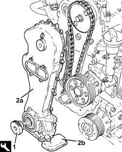
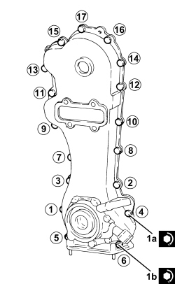
1. Tighten bolts (1a) and nuts (1b) securing the timing cover to the specified torque.
Follow the order shown in the figure for each tightening sequence. The tightening to 0.8 - 1.0 daNm is performed in two stages: a pretightening to 0.4 daNm followed by an additional tightening of 0.8 - 1.0 daNm.
| Component | Fastening | dia | Value (daNm) | Validity |
|---|---|---|---|---|
| Crankshaft oil seal front cover | Bolt | M6 | 0.8 ÷ 1.0 | 1.2 8v 1.4 8v 1.3 Multijet |
| Component | Fastening | dia | Value (daNm) | Validity |
|---|---|---|---|---|
| Crankshaft oil seal front cover | Nut | M6 | 0.8 ÷ 1.0 | 1.3 Multijet |
- Connect the engine oil vapour recirculation pipe fitting to the timing cover and tighten the bolts.
Ensure the o-ring is present and correctly positioned.
- Rotate the engine through 180° on the overhaul stand.
- Place the crankcase oil sump partition back in its housing and secure it using the bolts.
- Apply a strip of grey silicone sealant to the contact surfaces between the crankcase sump and lower engine block as shown in the diagram in the figure.
The sealant strip must be unbroken. The sealant strip diameter must be 3.0 -4.0 mm
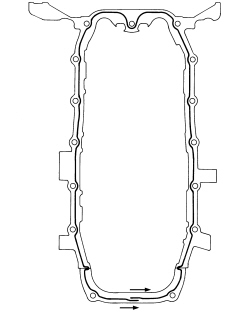
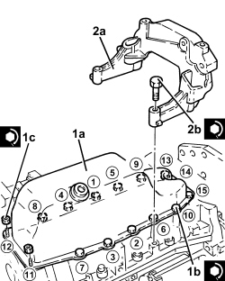
1. Position the crankcase sump (1a) in its housing and secure it tightening the bolts (1b) and the nuts (1c) to the recommended torque.
Follow the order shown in the figure for each tightening sequence. The tightening to 0.8 - 1.0 daNm is performed in two stages: a pretightening to 0.4 daNm followed by an additional tightening of 0.8 - 1.0 daNm.
| Component | Fastening | dia | Value (daNm) | Validity |
|---|---|---|---|---|
| Engine oil sump - lower engine crankcase side | Bolt | M6 | 0.8 ÷ 1.0 | 1.3 Multijet |
| Component | Fastening | dia | Value (daNm) | Validity |
|---|---|---|---|---|
| Engine oil sump - timing cover side | Nut | M6 | 0.8 ÷ 1.0 | 1.3 Multijet |
2. Place the bracket (2a) in its housing and secure it by tightening the bolts (2b) to the recommended torque.
| Component | Fastening | dia | Value (daNm) | Validity |
|---|---|---|---|---|
| Bracket joining manual gearbox/differential to engine | Bolt | M8 | 2.7 ÷ 3.3 | 1.3 Multijet 1.9 Multijet |
- Rotate the engine through 180° on the overhaul stand.
- Place the engine oil dipstick pipe back in its housing and fasten it with the bolt.
- Place the intermediate driveshaft mount in position and secure it tightening the bolts to the recommended torque.
| Component | Fastening | dia | Value (daNm) | Validity |
|---|---|---|---|---|
| Intermediate driveshaft bearing support | Bolt | M8 | 2.0 ÷ 2.4 | 1.3 Multijet |
- Remove the tool.
| Tool | Description | Function | Validity |
|---|---|---|---|
| 1870900600 | Hose | Timing cover centering | 1.3 Multijet |
- Position the crankcase pulley support flange in its housing and secure it with the left-threaded bolt without tightening it to the recommended torque.
- Place the water pump, complete with gasket in position, then tighten the bolts to the recommended torque.
| Component | Fastening | dia | Value (daNm) | Validity |
|---|---|---|---|---|
| Water pump | Nut | M6 | 0.8 ÷ 1.0 | 1.3 Multijet |
- Position the crankshaft pulley in its housing and secure it without tightening the bolts.
- Position the engine components single belt moving tensioner in its housing and secure it tightening the bolt to the recommended torque.
| Component | Fastening | dia | Value (daNm) | Validity |
|---|---|---|---|---|
| Engine components single belt moving tensioner | Bolt | M10 | 4.5 ÷ 5.5 | 1.3 Multijet |
- Adjust the mobile tensioner with a wrench and fit the auxiliary drive belt.
- Place the timing side rigid engine support in its housing with the engine lift bracket and secure it tightening the bolts to the recommended torque.
| Component | Fastening | dia | Value (daNm) | Validity |
|---|---|---|---|---|
| Timing side power unit rigid support | Bolt | M10 | 5.7 ÷ 6.3 | 1.3 Multijet |
- Place the turbocharger unit complete with catalytic conveter back in its housing and secure it by tightening the nuts to the recommended torque.
| Component | Fastening | dia | Value (daNm) | Validity |
|---|---|---|---|---|
| Turbocharger to exhaust manifold | Nut | M8 | 2.2 ÷ 2.7 | 1.3 Multijet |
- Refit the exhaust manifold heat shield with the engine lift bracket and secure with the nut and bolts.
- Position the pipe carrying engine oil to the turbocharger in its housing and secure it tightening connectors to the recommended torque.
Replace the copper washers on the connectors.
| Component | Fastening | dia | Value (daNm) | Validity |
|---|---|---|---|---|
| Engine oil supply pipe to turbocharger | Connector | M10 | 1.3 ÷ 1.6 | 1.3 Multijet |
- Position a new gasket between the crankcase and the engine oil return pipe to the turbocharger.
- Tighten the bolts securing the engine oil return pipe from the turbocharger, crankcase side, to the specified torque.
| Component | Fastening | dia | Value (daNm) | Validity |
|---|---|---|---|---|
| Engine oil supply pipe from turbocharger | Bolt | M6 | 0.8 ÷ 1.0 | 1.3 Multijet |
- Fit the protective strips to the oil filter and the engine oil heat exchanger.
- Place the electrical wiring in position and fasten it to the bands on the air capacity chamber.
- Connect the electrical connection to the E.G.R. solenoid valve.
- Connect the electrical connection to the fuel pressure regulator.
- Connect the electrical connection for the pressure relief sensor.
- Connect the electrical connection to the fuel pressure sensor.
- Refit the electrical wiring in its seat and secure.
- Tighten the bolts securing the wiring duct to the cylinder head.
- Connect the electrical connection for the air conditioning compressor engagement solenoid valve.
- Connect the electrical connection to the timing sensor.
- Connect the electrical connections to the injectors.
- Connect the electrical connections to the heater plugs.
- Connect the electrical connection to the engine oil pressure warning light switch.
- Connect the electrical connection for the engine rpm sensor.
- Connect the electrical connection to the engine coolant temperature sensor.
- Connect the electrical connection for the (pneumatic) throttle control solenoid valve.
- Remove the engine from the overhaul stand.
Removing
1. Undo the fastenings (1a) and remove the support complete with compressor and alternator (1b).
2. Remove the engine oil dipstick tube.
3. Undo the bolt and remove the detonation sensor.
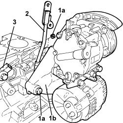
1. Fit the tool (1a), unscrew the bolt (1b) and remove the crankshaft gear (1c).
| Tool | Description | Function | Validity |
|---|---|---|---|
| 2000004500 | Template | Crankshaft timing | 1.2 8v 1.4 8v 1.4 16v |
2. Undo the bolt (2a) and remove the rpm sensor (2b).
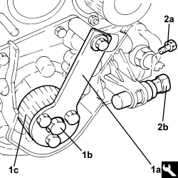
1. Undo the bolts (1a) and remove the rigid water return pipe to the pump (1b).
2. Undo the bolts (2a), nuts (2b) remove the water pump (2c).
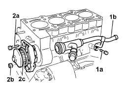
1. Remove the oil filter cartridge.
2. Remove the minimum engine oil pressure switch.
3. Undo the bolts (3a) and remove the engine block front cover (3b) with the built-in oil pump complete with crankshaft front oil seal (3c) and intake chamber (3d).
4. Remove the engine block front cover gasket.
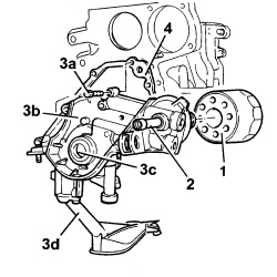
1. Undo the bolts (1a) and remove the crankshaft rear cover (1b).
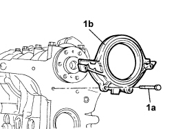
1. Undo the bolts (1a) and remove the connecting rod cap (1b).
2. Remove the lower crankpin half-bearings.
3. Remove the connecting rod - piston assemblies.
4. Remove the upper connecting rod half-bearings.
- Carry out the same operations for removing the remaining pistons.
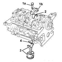
1. Check that the crankshaft endfloat is within specified limits.
| Measurement | Value | Validity |
|---|---|---|
| Crankshaft endfloat (mm) | 0.055 ÷ 0.265 | 1.2 8v 1.4 8v 1.3 Multijet |
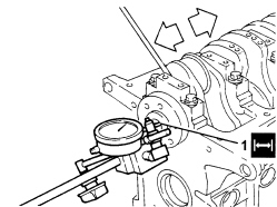
- If the value for the crankshaft endfloat does not correspond with the recommended figures, when refitting, regrind the crankcase seat and use suitable thrust washers (fastened to the central main bearing half) oversized by 0.127 mm.
1. Undo the bolts (1a) and remove the connecting rod caps (1b).
2. Remove the lower main journal half-bearings.
3. Remove the crankshaft.
4. Remove the upper main journal half-bearings.
The central main bearing half incorporates the crankshaft thrust ring halves.
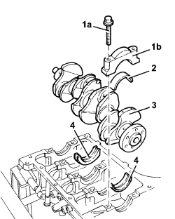
Op. 1084B18 ENGINE OIL PUMP, REMOVED - CHECK AT BENCH
- Unscrew the coolant chamber plugs from the crankcase.
- Remove the lubrication duct plug from the crankcase.
- Check the condition of the piston cooling oil sprays.
1. If oil sprays (1a) are blocked, remove them using tool (1b).
Insert the drift guide hole on the nozzle surface to prevent the drift from slipping and damaging the cylinder liner during the removal operation.
| Tool | Description | Function | Validity |
|---|---|---|---|
| 1860395000 | Picker | Engine oil jet removal | 1.2 8v 1.4 8v 1.4 16v |
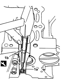
Refitting
- Wash and check the appearance of all compents removed.
- Tighten the water/oil sealing plugs to the upper crankcase.
1. Use the tool (1a) to fit new oil sprays (1b).
| Tool | Description | Function | Validity |
|---|---|---|---|
| 1860313000 | Fitting tool | Engine oil jet fitting | 1.2 8v 1.4 8v 1.4 16v |
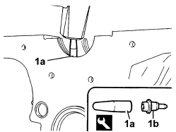
- Check that the planarity of the cylinder head support surface corresponds to the recommended figure; if this is not the case, regrind the cylinder head support surface.
| Measurement | Value | Validity |
|---|---|---|
| Cylinder head support surface flatness (mm) | < 0.1 | 1.2 8v 1.4 8v 1.4 16v 1.9 Multijet |
- Measure the diameter of the cylinder bores and check that they correspond to the recommended figures.
| Measurement | Value | Validity |
|---|---|---|
| Cylinder liner diameter - Grade A (mm) | 72.000 ÷ 72.010 | 1.4 8v 1.4 16v |
| Measurement | Value | Validity |
|---|---|---|
| Cylinder liner diameter - Grade B (mm) | 72.010 ÷ 72.020 | 1.4 8v 1.4 16v |
| Measurement | Value | Validity |
|---|---|---|
| Cylinder liner diameter - Grade C (mm) | 72.020 ÷ 72.030 | 1.4 8v 1.4 16v |
- Check that the ovality of the cylinder liners is within the recommended limits.
| Measurement | Value | Validity |
|---|---|---|
| Cylinder liner ovality (mm) | +/- 0.05 | 1.2 8v 1.4 8v 1.4 16v |
- Check that the taper of the cylinder liners/bores is within the recommended limits.
| Measurement | Value | Validity |
|---|---|---|
| Cylinder liner taper (mm) | +/- 0.005 | 1.2 8v 1.4 8v 1.4 16v |
- If the cylinder bore, taper or ovality measurements are not within the recommended limits, ream the cylinder bores following the recommended oversizes.
In the case of reaming, all the bores must have the same oversize.
| Measurement | Value | Validity |
|---|---|---|
| Cylinder liner diameter oversize (mm) | 0.1 | 1.2 8v 1.4 8v 1.4 16v 1.3 Multijet 1.9 Multijet |
- Check that the diameter of the main journals corresponds to the recommended figures.
| Measurement | Value | Validity |
|---|---|---|
| Main journal diameter - Category A (mm) | 47.997 ÷ 48.003 | 1.4 8v 1.4 16v |
| Measurement | Value | Validity |
|---|---|---|
| Main journal diameter - Category B (mm) | 47.988 ÷ 47.994 | 1.4 8v 1.4 16v |
| Measurement | Value | Validity |
|---|---|---|
| Main journal diameter - Category C (mm) | 47.982 ÷ 47.988 | 1.4 8v 1.4 16v |
- If the diameter of the main journals is not correct, they should be reground to the recommended undersize.
Because the crankshaft has undergone nitriding, this treatment should be repeated and the size re-checked if it is ground.
| Measurement | Value | Validity |
|---|---|---|
| Main journal diameter undersize (mm) | 0.127 | 1.2 8v 1.4 8v 1.4 16v 1.3 Multijet |
- Check that the diameter of the crankpins corresponds to the recommended figures.
| Measurement | Value | Validity |
|---|---|---|
| Crankpin diameter (mm) | 41.990 ÷ 42.008 | 1.2 8v 1.4 8v 1.4 16v |
- If the diameter of the crankpins is not correct, they should be reground to the recommended undersize.
Because the crankshaft has undergone nitriding, this treatment should be repeated and the size re-checked if it is ground.
| Measurement | Value | Validity |
|---|---|---|
| Crankpin diameter undersize (mm) | 0.127 | 1.2 8v 1.4 8v 1.4 16v 1.3 Multijet 1.9 Multijet |
- Fit the crankshaft into its seat on the crankcase.
- Fit the calibrated wire (plastigage) for measuring the main journal backlash.
- Refit the connecting rod caps complete with half-bearings and secure them by tightening the bolts to the recommended torque.
| Component | Fastening | dia | Value (daNm) | Validity |
|---|---|---|---|---|
| Bearing caps | Bolt | M10 | 1.9 ÷ 2.1 + 90° +/- 3° | 1.2 8v 1.4 8v |
- Check that the diameter of the main journals corresponds to the recommended figures.
| Measurement | Value | Validity |
|---|---|---|
| Main journal seat diameter - Category 1 (mm) | 51.705 ÷ 51.709 | 1.2 8v 1.4 8v |
| Measurement | Value | Validity |
|---|---|---|
| Main journal seat diameter - Category 2 (mm) | 51.709 ÷ 51.713 | 1.2 8v 1.4 8v |
| Measurement | Value | Validity |
|---|---|---|
| Main journal seat diameter - Category 3 (mm) | 51.713 ÷ 51.717 | 1.2 8v 1.4 8v |
- The size of the main journal half-bearings is given.
| Measurement | Value | Validity |
|---|---|---|
| Main journal half-bearings - Category 1 (Red) (mm) | 1.836 ÷ 1.840 | 1.2 8v 1.4 8v 1.4 16v |
| Measurement | Value | Validity |
|---|---|---|
| Main journal half-bearings - Category 2 (Blue) (mm) | 1.843 ÷ 1.847 | 1.2 8v 1.4 8v 1.4 16v |
| Measurement | Value | Validity |
|---|---|---|
| Main journal half-bearings - Category 3 (Yellow) (mm) | 1.848 ÷ 1.852 | 1.2 8v 1.4 8v 1.4 16v |
| Measurement | Value | Validity |
|---|---|---|
| Main journal half-bearing thickness oversize (mm) | 0.254 ÷ 0.508 | 1.4 8v |
- Remove the main bearing caps and check the main journal backlash. Use an appropriate gauge to measure the width of the plastigage.
Check one main journal at a time, without rotating the crankshaft.
| Measurement | Value | Validity |
|---|---|---|
| Clearance between main bearings - crankshaft main journals (mm) | 0.025 ÷ 0.040 | 1.2 8v 1.4 8v 1.4 16v |
- After checking all the main journals, refit the main bearing caps with half-bearings and secure by tightening the bolts to the specified torque.
| Component | Fastening | dia | Value (daNm) | Validity |
|---|---|---|---|---|
| Bearing caps | Bolt | M10 | 1.9 ÷ 2.1 + 90° +/- 3° | 1.2 8v 1.4 8v |
Op. 1028H54 PISTON WITH CONNECTING ROD - DISMANTLING AT THE BENCH
- Clean any carbon residues carefully from the pistons.
- Check that the outer diameter of the pistons corresponds to the recommended figures; if not, replace the piston complete with piston rings and gudgeon pin.
| Measurement | Value | Validity |
|---|---|---|
| Piston outer diameter -Grade A (mm) | 71.960 ÷ 71.970 | 1.4 8v 1.4 16v |
| Measurement | Value | Validity |
|---|---|---|
| Piston outer diameter - Grade B (mm) | 71.970 ÷ 71.980 | 1.4 8v 1.4 16v |
| Measurement | Value | Validity |
|---|---|---|
| Piston outer diameter - Grade C (mm) | 71.980 ÷ 71.990 | 1.4 8v 1.4 16v |
Measure perpendicular to the gudgeon pin axis, 9 mm from the lower edge of the skirt.
- Position the piston in the cylinder liner and use a feeler gauge to measure the specified clearance.
- Check that the pin seat bore diameter is within specified values, otherwise replace the pin with an oversized pin.
| Measurement | Value | Validity |
|---|---|---|
| Gudgeon pin housing diameter in pistons (mm) | 17.982 ÷ 17.986 | 1.2 8v 1.4 8v |
| Measurement | Value | Validity |
|---|---|---|
| Piston gudgeon pin diameter oversize (mm) | 1.2 8v 1.4 8v |
- Check that the outer diameter of the gudgeon pins is within the recommended limits; if not, replace the worn gudgeon pins.
| Measurement | Value | Validity |
|---|---|---|
| Piston pin outer diameter (mm) | 17.970 ÷ 17.974 | 1.2 8v 1.4 8v 1.4 16v |
- Check that the piston ring seats are within the recommended values.
| Measurement | Value | Validity |
|---|---|---|
| Piston ring seat in piston - 1st groove (mm) | 1.020 ÷ 1.040 | 1.4 8v 1.4 16v |
| Measurement | Value | Validity |
|---|---|---|
| Piston ring seat in piston - 2nd groove (mm) | 1.210 ÷ 1.230 | 1.4 8v 1.4 16v |
| Measurement | Value | Validity |
|---|---|---|
| Piston ring seat in piston - 3rd groove (mm) | 2.010 ÷ 2.030 | 1.4 8v 1.4 16v |
- Check that the thickness of the piston rings is within the recommended limits.
| Measurement | Value | Validity |
|---|---|---|
| Cylinder compression 1st piston ring thickness (mm) | 0.970 ÷ 0.990 | 1.4 8v 1.4 16v |
| Measurement | Value | Validity |
|---|---|---|
| Cylinder compression 2nd piston ring thickness (mm) | 1.170 ÷ 1.190 | 1.4 8v 1.4 16v |
| Measurement | Value | Validity |
|---|---|---|
| Cylinder compression 3rd piston ring thickness (mm) | 1.975 ÷ 1.990 | 1.4 8v 1.4 16v |
| Measurement | Value | Validity |
|---|---|---|
| Seal oversize (mm) | 0.1 | 1.2 8v 1.4 8v 1.4 16v |
- Fit the sealing rings in the cylinder liner and check the gap between the seal ends is within specified limits. Otherwise replace the sealing rings.
| Measurement | Value | Validity |
|---|---|---|
| Cylinder compression 1st piston ring gap (mm) | 0.20 ÷ 0.40 | 1.4 8v |
| Measurement | Value | Validity |
|---|---|---|
| Cylinder compression 2nd piston ring gap (mm) | 0.50 ÷ 0.70 | 1.4 8v |
| Measurement | Value | Validity |
|---|---|---|
| Cylinder compression 3rd piston ring gap (mm) | 0.20 ÷ 0.40 | 1.4 8v |
- Check that the mating clearance between the piston rings and the grooves on the piston is within specified limits.
| Measurement | Value | Validity |
|---|---|---|
| Cylinder compression 1st piston ring endfloat (mm) | 0.030 ÷ 0.070 | 1.4 8v 1.4 16v |
| Measurement | Value | Validity |
|---|---|---|
| Cylinder compression 2nd piston ring endfloat (mm) | 0.020 ÷ 0.060 | 1.4 8v 1.4 16v |
| Measurement | Value | Validity |
|---|---|---|
| Cylinder compression 3rd piston ring endfloat (mm) | 0.020 ÷ 0.055 | 1.4 8v 1.4 16v |
Op. 1028H54 PISTON WITH CONNECTING ROD - DISMANTLING AT THE BENCH
Op. 1084B18 ENGINE OIL PUMP, REMOVED - CHECK AT BENCH
- Fit the connecting rod-piston assemblies and align in accordance with the following references.
1. Piston class and arrow indicating timing side.
2. Area where the number of the matching cylinder liner is stamped.
3. Piston pin offset
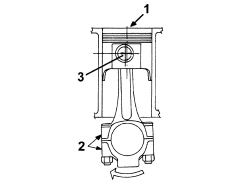
- Fit the connecting rod-piston assemblies with half-bearings using the tool to compress the piston rings and then fit the piston into the liner.
- Rotate the engine through 180° on the overhaul stand.
- Apply the calibrated wire (plastigate) for measuring the crankpin clearance.
- Refit the connecting rod caps complete with half-bearings and secure them by tightening the bolts to the recommended torque.
The connecting rod caps are fracture type. If replaced, they are supplied pre-fractured by the manufacturer.
Check that the parts are free of burrs, blisters, scratches or any other surface defect. Before installation, parts must be thorougly washed, cleaned and dried. Fit the connecting rod caps so that the number stamped on each cap faces towards the same side as the number stamped on the big end.
Each connecting rod must be paired with its cap, respecting the numerical references stamped on the parts. Connecting rods and connecting rod caps are not interchangeable.
| Component | Fastening | dia | Value (daNm) | Validity |
|---|---|---|---|---|
| Connecting rod big end bearing caps | Bolt | M8 | 1.9 ÷ 2.1 + 40° +/- 2° | 1.2 8v 1.4 8v 1.4 16v 1.3 Multijet |
- Check that the diameter of the crankpins corresponds to the recommended figures.
| Measurement | Value | Validity |
|---|---|---|
| Crankpin seat diameter (mm) | 45.128 ÷ 45.138 | 1.2 8v 1.4 8v |
- The size of the connecting rod half-bearings is given.
| Measurement | Value | Validity |
|---|---|---|
| Connecting rod half-bearing thickness (mm) | 1.544 ÷ 1.548 | 1.2 8v 1.4 8v 1.4 16v |
| Measurement | Value | Validity |
|---|---|---|
| Connecting rod half-bearing thickness oversize (mm) | 0.254 ÷ 0.508 | 1.2 8v 1.4 8v |
- Remove the connecting rod caps and check the crankpin backlash. Use an appropriate gauge to measure the width of the plastigage.
| Measurement | Value | Validity |
|---|---|---|
| Clearance between connectring rod bearings - crankpins (mm) | 0.021 ÷ 0.060 | 1.2 8v 1.4 8v |
Check one crankpin at a time, without rotating the crankshaft.
- If the value measured is not within the recommended figures, replace the connecting rod bearings.
- Refit the connecting rod caps complete with half-bearings and secure them by tightening the bolts to the recommended torque.
| Component | Fastening | dia | Value (daNm) | Validity |
|---|---|---|---|---|
| Connecting rod big end bearing caps | Bolt | M8 | 1.9 ÷ 2.1 + 40° +/- 2° | 1.2 8v 1.4 8v 1.4 16v 1.3 Multijet |
- Position a new oil pump gasket.
- Fit the front crankcase cover with built-in oil pump complete with intake chamber and secure by tightening bolts to the specified torque.
- Fit the engine oil filter.
- Fit the minimum engine oil pressure switch.
- Fit the oil seal to the crankshaft front cover using the tool.
| Tool | Description | Function | Validity |
|---|---|---|---|
| 1860903000 | Fitting tool | Fitting crankshaft front oil seal | 1.2 8v 1.4 8v |
- Fit the crankcase rear cover and secure by tightening the bolts to the specified torque.
| Component | Fastening | dia | Value (daNm) | Validity |
|---|---|---|---|---|
| Crankshaft to crankcase rear cover | Bolt | M6 | 0.8 ÷ 1.0 | 1.2 8v 1.4 8v 1.4 16v |
- Fit a new rear camshaft oil seal using the tools.
| Tool | Description | Function | Validity |
|---|---|---|---|
| 1860879000 | Grip | Fitting crankshaft rear oil seal | 1.2 8v 1.4 8v |
| Tool | Description | Function | Validity |
|---|---|---|---|
| 1860881000 | Fitting tool | Fitting crankshaft rear oil seal | 1.2 8v 1.4 8v |
- Fit the water pump and secure with the bolts and nut.
- Fit the rigid coolant return pipe to the pump and secure to the crankcase with the bolt.
- Fit the crankshaft gear.
- Position the tool and tighten the crankshaft gear bolt to the specified torque.
| Tool | Description | Function | Validity |
|---|---|---|---|
| 2000004500 | Template | Crankshaft timing | 1.2 8v 1.4 8v 1.4 16v |
| Component | Fastening | dia | Value (daNm) | Validity |
|---|---|---|---|---|
| Crankshaft gear | Bolt | M11 | 1.9 ÷ 2.1 + 90° +/- 3° | 1.2 8v 1.4 8v |
- Remove the tool fitted previously.
- Rotate the engine on the overhaul stand.
- Clean the crankcase and oil sump contact surfaces, removing the silicon sealant residues.
- Apply the silicone sealant continuously without any breaks over the entire perimeter of the crankcase sump.
Join the end to the beginning seamlessly.
- Fit the crankcase sump and secure it by tightening the bolts and the nuts to the specified torque.
When positioning the crankcase sump, avoid significant sideways movements that could remove the sealant.
| Component | Fastening | dia | Value (daNm) | Validity |
|---|---|---|---|---|
| Engine oil sump - crankcase side | Bolt | M8 | 2.2 ÷ 2.7 | 1.2 8v 1.4 8v |
| Component | Fastening | dia | Value (daNm) | Validity |
|---|---|---|---|---|
| Engine oil sump - rear cover side and oil pump side | Nut | M6 | 0.8 ÷ 1.0 | 1.2 8v 1.4 8v |
- Clean the contact surfaces between the cylinder head and engine block.
- Fit the locating bushes for the cylinder block/crankcase.
- Position the cylinder head gasket on the cylinder block/crankcase.
1. Fit the cylinder head and tighten the fixing bolts to the recommended torque.
| Component | Fastening | dia | Value (daNm) | Validity |
|---|---|---|---|---|
| Cylinder head | Bolt | M9 | 2.9 ÷ 3.1 + 90° + 90° +/- 3° | 1.2 8v 1.4 8v |
Follow the order illustrated below for the tightening of the cylinder head bolts.
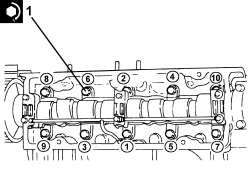
- Fit the intake chamber and tighten the nuts to the specified torque.
| Component | Fastening | dia | Value (daNm) | Validity |
|---|---|---|---|---|
| Intake manifold | Nut | M8 | 2.3 ÷ 2.8 | 1.2 8v 1.4 8v 1.9 Multijet |
1. Fit the template to the camshaft rear shank.
| Tool | Description | Function | Validity |
|---|---|---|---|
| 2000004400 | Template | Camshaft timing | 1.2 8v 1.4 8v |
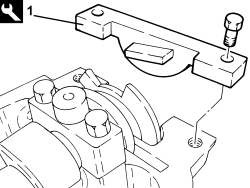
1. Fit the timing belt.
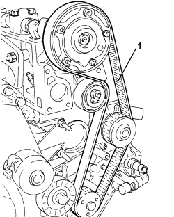
1. Fit the crankshaft timing template to the drive pulley.
| Tool | Description | Function | Validity |
|---|---|---|---|
| 2000004500 | Template | Crankshaft timing | 1.2 8v 1.4 8v 1.4 16v |
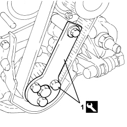
1. Proceed as shown in the figure to adjust the automatic tensioner reference fork until it is in contact.
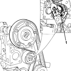
1. Fit the reaction tool (1a) and tighten the variable valve timing bolt (1b) to the specified torque.
| Tool | Description | Function | Validity |
|---|---|---|---|
| 2000004200 | Counter-torque | Timing driven pulley lock | 1.4 8v |
| Component | Fastening | dia | Value (daNm) | Validity |
|---|---|---|---|---|
| Phase transformer | Bolt | M12 | 1.9 ÷ 2.1 + 55° +/- 2° | 1.4 8v |
- Fit the variable valve timing bolt plug and secure to the specified torque.
| Component | Fastening | dia | Value (daNm) | Validity |
|---|---|---|---|---|
| Phase transformer sealing plug | Plug | M27 | 2.4 ÷ 3.0 | 1.4 8v |
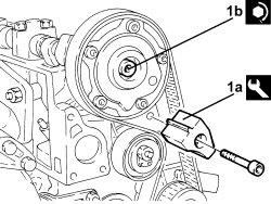
- Remove both templates and the reaction tool fitted previously and turn the engine through a couple of revolutions to settle the timing belt.
- Loosen the belt tensioner nut and adjust the front fork until it is aligned with the rear fork.
- Tighten the belt tensioner nut to the recommended torque.
| Component | Fastening | dia | Value (daNm) | Validity |
|---|---|---|---|---|
| Timing moving tensioner | Nut | M8 | 2.5 ÷ 3.1 | 1.2 8v 1.4 8v |
- Fit the templates removed previously to check the engine timing adjustment.
1. Position cam cover (1a) on the cylinder head and tighten bolts (1b).
2. Fit the tappet cover locating tool.
| Tool | Description | Function | Validity |
|---|---|---|---|
| 2000004300 | Template | Tappet cover centering | 1.4 8v |
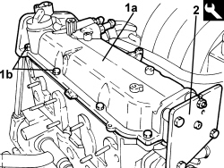
- Tighten the previously screwed in cam cover bolts to the specified torque.
| Component | Fastening | dia | Value (daNm) | Validity |
|---|---|---|---|---|
| Tappet cover | Bolt | M6 | 0.8 ÷ 1.0 | 1.2 8v 1.4 8v 1.3 Multijet 1.9 Multijet |
- Remove the tappet cover locating tool fitted previously.
1. Fit the timing sensor.
2. Fit the injection control unit mount.
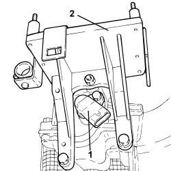
- Fit the rpm sensor and tighten the bolt.
- Fit the knock sensor and tighten the bolt to the specified torque.
| Component | Fastening | dia | Value (daNm) | Validity |
|---|---|---|---|---|
| Detonation sensor | Bolt (to be replaced) | M8 | 2.2 ÷ 2.7 | 1.2 8v 1.4 8v 1.4 16v |
- Fit the engine oil dipstick tube.
- Fit the mount with compressor and alternator and secure the fastenings.
| Component | Fastening | dia | Value (daNm) | Validity |
|---|---|---|---|---|
| Compressor support | Bolt | M10x1.25 | 4.5 ÷ 5.5 | 1.2 8v |
| Component | Fastening | dia | Value (daNm) | Validity |
|---|---|---|---|---|
| Compressor support | Nut | M8x1.25 | 2.3 ÷ 2.7 | 1.2 8v |
| Component | Fastening | dia | Value (daNm) | Validity |
|---|---|---|---|---|
| Compressor support | Nut | M10x1.25 | 4.5 ÷ 5.5 | 1.2 8v |
- Fit the timing belt protective covers and secure them using the bolts.
- Fit the crankshaft pulley and tighten the bolts to the recommended torque.
| Component | Fastening | dia | Value (daNm) | Validity |
|---|---|---|---|---|
| Services pulley on crankshaft | Bolt | M8 | 2.3 ÷ 2.8 |
- Fit the auxiliary drivebelt by adjusting the automatic belt tensioner.
- Fit the timing side rigid power unit mount and tighten the bolts to the specified torque.
| Component | Fastening | dia | Value (daNm) | Validity |
|---|---|---|---|---|
| Timing side power unit rigid support | Bolt | M10 | 5.4 ÷ 6.6 | 1.2 8v 1.4 8v 1.4 16v |
- Connect the electrical connection for the coolant temperature sensor.
- Connect the electrical connection for the timing sensor.
- Connect the electrical connection of the ignition coil module.
- Connect the electrical connection for the throttle casing.
- Connect the electrical connection for the knock sensor.
- Connect the air conditioning compressor electrical connection.
- Connect the earth lead to the crankcase.
- Connect the electrical connection for the absolute pressure sensor.
- Connect the electrical connection for the air pressure/temperature sensor.
- Connect the electrical connection for the variable valve timing electromagnet.
- Remove the engine from the overhaul stand.
Removing
1. Undo the fastenings (1a) and remove the support complete with compressor and alternator (1b).
2. Remove the engine oil dipstick tube.
3. Undo the bolt and remove the detonation sensor.
1. Fit the tool (1a), unscrew the bolt (1b) and remove the crankshaft gear (1c).
| Tool | Description | Function | Validity |
|---|---|---|---|
| 2000004500 | Template | Crankshaft timing | 1.2 8v 1.4 8v 1.4 16v |
2. Undo the bolt (2a) and remove the rpm sensor (2b).
1. Undo the bolts (1a) and remove the rigid water return pipe to the pump (1b).
2. Undo the bolts (2a), nuts (2b) remove the water pump (2c).
1. Remove the oil filter cartridge.
2. Remove the minimum engine oil pressure switch.
3. Undo the bolts (3a) and remove the engine block front cover (3b) with the built-in oil pump complete with crankshaft front oil seal (3c) and intake chamber (3d).
4. Remove the engine block front cover gasket.
1. Undo the bolts (1a) and remove the crankshaft rear cover (1b).
1. Undo the bolts (1a) and remove the connecting rod cap (1b).
2. Remove the lower crankpin half-bearings.
3. Remove the connecting rod - piston assemblies.
4. Remove the upper connecting rod half-bearings.
- Carry out the same operations for removing the remaining pistons.
1. Check that the crankshaft endfloat is within specified limits.
| Measurement | Value | Validity |
|---|---|---|
| Crankshaft endfloat (mm) | 0.055 ÷ 0.265 | 1.2 8v 1.4 8v 1.3 Multijet |
- If the value for the crankshaft endfloat does not correspond with the recommended figures, when refitting, regrind the crankcase seat and use suitable thrust washers (fastened to the central main bearing half) oversized by 0.127 mm.
1. Undo the bolts (1a) and remove the connecting rod caps (1b).
2. Remove the lower main journal half-bearings.
3. Remove the crankshaft.
4. Remove the upper main journal half-bearings.
The central main bearing half incorporates the crankshaft thrust ring halves.
Op. 1084B18 ENGINE OIL PUMP, REMOVED - CHECK AT BENCH
- Unscrew the coolant chamber plugs from the crankcase.
- Remove the lubrication duct plug from the crankcase.
- Check the condition of the piston cooling oil sprays.
1. If oil sprays (1a) are blocked, remove them using tool (1b).
Insert the drift guide hole on the nozzle surface to prevent the drift from slipping and damaging the cylinder liner during the removal operation.
| Tool | Description | Function | Validity |
|---|---|---|---|
| 1860395000 | Picker | Engine oil jet removal | 1.2 8v 1.4 8v 1.4 16v |
Refitting
- Wash and check the appearance of all compents removed.
- Tighten the water/oil sealing plugs to the upper crankcase.
1. Use the tool (1a) to fit new oil sprays (1b).
| Tool | Description | Function | Validity |
|---|---|---|---|
| 1860313000 | Fitting tool | Engine oil jet fitting | 1.2 8v 1.4 8v 1.4 16v |
- Check that the planarity of the cylinder head support surface corresponds to the recommended figure; if this is not the case, regrind the cylinder head support surface.
| Measurement | Value | Validity |
|---|---|---|
| Cylinder head support surface flatness (mm) | < 0.1 | 1.2 8v 1.4 8v 1.4 16v 1.9 Multijet |
- Measure the diameter of the cylinder bores and check that they correspond to the recommended figures.
| Measurement | Value | Validity |
|---|---|---|
| Cylinder liner diameter - Grade A (mm) | 70.800 ÷ 70.810 | 1.2 8v |
| Measurement | Value | Validity |
|---|---|---|
| Cylinder liner diameter - Grade B (mm) | 70.810 ÷ 70.820 | 1.2 8v |
| Measurement | Value | Validity |
|---|---|---|
| Cylinder liner diameter - Grade C (mm) | 70.820 ÷ 70.830 | 1.2 8v |
- Check that the ovality of the cylinder liners is within the recommended limits.
| Measurement | Value | Validity |
|---|---|---|
| Cylinder liner ovality (mm) | +/- 0.05 | 1.2 8v 1.4 8v 1.4 16v |
- Check that the taper of the cylinder liners/bores is within the recommended limits.
| Measurement | Value | Validity |
|---|---|---|
| Cylinder liner taper (mm) | +/- 0.005 | 1.2 8v 1.4 8v 1.4 16v |
- If the cylinder bore, taper or ovality measurements are not within the recommended limits, ream the cylinder bores following the recommended oversizes.
In the case of reaming, all the bores must have the same oversize.
| Measurement | Value | Validity |
|---|---|---|
| Cylinder liner diameter oversize (mm) | 0.1 | 1.2 8v 1.4 8v 1.4 16v 1.3 Multijet 1.9 Multijet |
- Check that the diameter of the main journals corresponds to the recommended figures.
| Measurement | Value | Validity |
|---|---|---|
| Main journal diameter - Category A (mm) | 47.994 ÷ 48.000 | 1.2 8v |
| Measurement | Value | Validity |
|---|---|---|
| Main journal diameter - Category B (mm) | 47.988 ÷ 47.994 | 1.2 8v |
| Measurement | Value | Validity |
|---|---|---|
| Main journal diameter - Category C (mm) | 47.982 ÷ 47.988 | 1.2 8v |
- If the diameter of the main journals is not correct, they should be reground to the recommended undersize.
Because the crankshaft has undergone nitriding, this treatment should be repeated and the size re-checked if it is ground.
| Measurement | Value | Validity |
|---|---|---|
| Main journal diameter undersize (mm) | 0.127 | 1.2 8v 1.4 8v 1.4 16v 1.3 Multijet |
- Check that the diameter of the crankpins corresponds to the recommended figures.
| Measurement | Value | Validity |
|---|---|---|
| Crankpin diameter (mm) | 41.990 ÷ 42.008 | 1.2 8v 1.4 8v 1.4 16v |
- If the diameter of the crankpins is not correct, they should be reground to the recommended undersize.
Because the crankshaft has undergone nitriding, this treatment should be repeated and the size re-checked if it is ground.
| Measurement | Value | Validity |
|---|---|---|
| Crankpin diameter undersize (mm) | 0.127 | 1.2 8v 1.4 8v 1.4 16v 1.3 Multijet 1.9 Multijet |
- Fit the crankshaft into its seat on the crankcase.
- Fit the calibrated wire (plastigage) for measuring the main journal backlash.
- Refit the connecting rod caps complete with half-bearings and secure them by tightening the bolts to the recommended torque.
| Component | Fastening | dia | Value (daNm) | Validity |
|---|---|---|---|---|
| Bearing caps | Bolt | M10 | 1.9 ÷ 2.1 + 90° +/- 3° | 1.2 8v 1.4 8v |
- Check that the diameter of the main journals corresponds to the recommended figures.
| Measurement | Value | Validity |
|---|---|---|
| Main journal seat diameter - Category 1 (mm) | 51.705 ÷ 51.709 | 1.2 8v 1.4 8v |
| Measurement | Value | Validity |
|---|---|---|
| Main journal seat diameter - Category 2 (mm) | 51.709 ÷ 51.713 | 1.2 8v 1.4 8v |
| Measurement | Value | Validity |
|---|---|---|
| Main journal seat diameter - Category 3 (mm) | 51.713 ÷ 51.717 | 1.2 8v 1.4 8v |
- The size of the main journal half-bearings is given.
| Measurement | Value | Validity |
|---|---|---|
| Main journal half-bearings - Category 1 (Red) (mm) | 1.836 ÷ 1.840 | 1.2 8v 1.4 8v 1.4 16v |
| Measurement | Value | Validity |
|---|---|---|
| Main journal half-bearings - Category 2 (Blue) (mm) | 1.843 ÷ 1.847 | 1.2 8v 1.4 8v 1.4 16v |
| Measurement | Value | Validity |
|---|---|---|
| Main journal half-bearings - Category 3 (Yellow) (mm) | 1.848 ÷ 1.852 | 1.2 8v 1.4 8v 1.4 16v |
| Measurement | Value | Validity |
|---|---|---|
| Main journal half-bearing thickness oversize (mm) | 0.254 ÷ 0.508 | 1.4 8v |
- Remove the main bearing caps and check the main journal backlash. Use an appropriate gauge to measure the width of the plastigage.
Check one main journal at a time, without rotating the crankshaft.
| Measurement | Value | Validity |
|---|---|---|
| Clearance between main bearings - crankshaft main journals (mm) | 0.025 ÷ 0.040 | 1.2 8v 1.4 8v 1.4 16v |
- After checking all the main journals, refit the main bearing caps with half-bearings and secure by tightening the bolts to the specified torque.
| Component | Fastening | dia | Value (daNm) | Validity |
|---|---|---|---|---|
| Bearing caps | Bolt | M10 | 1.9 ÷ 2.1 + 90° +/- 3° | 1.2 8v 1.4 8v |
Op. 1028H54 PISTON WITH CONNECTING ROD - DISMANTLING AT THE BENCH
- Clean any carbon residues carefully from the pistons.
- Check that the outer diameter of the pistons corresponds to the recommended figures; if not, replace the piston complete with piston rings and gudgeon pin.
| Measurement | Value | Validity |
|---|---|---|
| Piston outer diameter -Grade A (mm) | 70.760 ÷ 70.770 | 1.2 8v |
| Measurement | Value | Validity |
|---|---|---|
| Piston outer diameter - Grade B (mm) | 70.770 ÷ 70.780 | 1.2 8v |
| Measurement | Value | Validity |
|---|---|---|
| Piston outer diameter - Grade C (mm) | 70.780 ÷ 70.790 | 1.2 8v |
Measure perpendicular to the gudgeon pin axis, 6 mm from the lower edge of the skirt.
- Position the piston in the cylinder liner and use a feeler gauge to measure the specified clearance.
- Check that the pin seat bore diameter is within specified values, otherwise replace the pin with an oversized pin.
| Measurement | Value | Validity |
|---|---|---|
| Gudgeon pin housing diameter in pistons (mm) | 17.982 ÷ 17.986 | 1.2 8v 1.4 8v |
| Measurement | Value | Validity |
|---|---|---|
| Piston gudgeon pin diameter oversize (mm) | 1.2 8v 1.4 8v |
- Check that the outer diameter of the gudgeon pins is within the recommended limits; if not, replace the worn gudgeon pins.
| Measurement | Value | Validity |
|---|---|---|
| Piston pin outer diameter (mm) | 17.970 ÷ 17.974 | 1.2 8v 1.4 8v 1.4 16v |
- Check that the piston ring seats are within the recommended values.
| Measurement | Value | Validity |
|---|---|---|
| Piston ring seat in piston - 1st groove (mm) | 1.230 ÷ 1.250 | 1.2 8v |
| Measurement | Value | Validity |
|---|---|---|
| Piston ring seat in piston - 2nd groove (mm) | 1.210 ÷ 1.230 | 1.2 8v |
| Measurement | Value | Validity |
|---|---|---|
| Piston ring seat in piston - 3rd groove (mm) | 2.510 ÷ 2.530 | 1.2 8v |
- Check that the thickness of the piston rings is within the recommended limits.
| Measurement | Value | Validity |
|---|---|---|
| Cylinder compression 1st piston ring thickness (mm) | 1.175 ÷ 1.190 | 1.2 8v |
| Measurement | Value | Validity |
|---|---|---|
| Cylinder compression 2nd piston ring thickness (mm) | 1.170 ÷ 1.190 | 1.2 8v |
| Measurement | Value | Validity |
|---|---|---|
| Cylinder compression 3rd piston ring thickness (mm) | 2.475 ÷ 2.490 | 1.2 8v |
| Measurement | Value | Validity |
|---|---|---|
| Seal oversize (mm) | 0.1 | 1.2 8v 1.4 8v 1.4 16v |
- Fit the sealing rings in the cylinder liner and check the gap between the seal ends is within specified limits. Otherwise replace the sealing rings.
| Measurement | Value | Validity |
|---|---|---|
| Cylinder compression 1st piston ring gap (mm) | 0.20 ÷ 0.40 | 1.2 8v |
| Measurement | Value | Validity |
|---|---|---|
| Cylinder compression 2nd piston ring gap (mm) | 0.25 ÷ 0.70 | 1.2 8v |
| Measurement | Value | Validity |
|---|---|---|
| Cylinder compression 3rd piston ring gap (mm) | 0.20 ÷ 0.45 | 1.2 8v |
- Check that the mating clearance between the piston rings and the grooves on the piston is within specified limits.
| Measurement | Value | Validity |
|---|---|---|
| Cylinder compression 1st piston ring endfloat (mm) | 0.020 ÷ 0.060 | 1.2 8v |
| Measurement | Value | Validity |
|---|---|---|
| Cylinder compression 2nd piston ring endfloat (mm) | 0.020 ÷ 0.060 | 1.2 8v |
| Measurement | Value | Validity |
|---|---|---|
| Cylinder compression 3rd piston ring endfloat (mm) | 0.020 ÷ 0.055 | 1.2 8v |
Op. 1028H54 PISTON WITH CONNECTING ROD - DISMANTLING AT THE BENCH
Op. 1084B18 ENGINE OIL PUMP, REMOVED - CHECK AT BENCH
- Fit the connecting rod-piston assemblies and align in accordance with the following references.
1. Piston class and arrow indicating timing side.
2. Area where the number of the matching cylinder liner is stamped.
3. Piston pin offset
- Fit the connecting rod-piston assemblies with half-bearings using the tool to compress the piston rings and then fit the piston into the liner.
- Rotate the engine through 180° on the overhaul stand.
- Apply the calibrated wire (plastigate) for measuring the crankpin clearance.
- Refit the connecting rod caps complete with half-bearings and secure them by tightening the bolts to the recommended torque.
The connecting rod caps are fracture type. If replaced, they are supplied pre-fractured by the manufacturer.
Check that the parts are free of burrs, blisters, scratches or any other surface defect. Before installation, parts must be thorougly washed, cleaned and dried. Fit the connecting rod caps so that the number stamped on each cap faces towards the same side as the number stamped on the big end.
Each connecting rod must be paired with its cap, respecting the numerical references stamped on the parts. Connecting rods and connecting rod caps are not interchangeable.
| Component | Fastening | dia | Value (daNm) | Validity |
|---|---|---|---|---|
| Connecting rod big end bearing caps | Bolt | M8 | 1.9 ÷ 2.1 + 40° +/- 2° | 1.2 8v 1.4 8v 1.4 16v 1.3 Multijet |
- Check that the diameter of the crankpins corresponds to the recommended figures.
| Measurement | Value | Validity |
|---|---|---|
| Crankpin seat diameter (mm) | 45.128 ÷ 45.138 | 1.2 8v 1.4 8v |
- The size of the connecting rod half-bearings is given.
| Measurement | Value | Validity |
|---|---|---|
| Connecting rod half-bearing thickness (mm) | 1.544 ÷ 1.548 | 1.2 8v 1.4 8v 1.4 16v |
| Measurement | Value | Validity |
|---|---|---|
| Connecting rod half-bearing thickness oversize (mm) | 0.254 ÷ 0.508 | 1.2 8v 1.4 8v |
- Remove the connecting rod caps and check the crankpin backlash. Use an appropriate gauge to measure the width of the plastigage.
| Measurement | Value | Validity |
|---|---|---|
| Clearance between connectring rod bearings - crankpins (mm) | 0.021 ÷ 0.060 | 1.2 8v 1.4 8v |
Check one crankpin at a time, without rotating the crankshaft.
- If the value measured is not within the recommended figures, replace the connecting rod bearings.
- Refit the connecting rod caps complete with half-bearings and secure them by tightening the bolts to the recommended torque.
| Component | Fastening | dia | Value (daNm) | Validity |
|---|---|---|---|---|
| Connecting rod big end bearing caps | Bolt | M8 | 1.9 ÷ 2.1 + 40° +/- 2° | 1.2 8v 1.4 8v 1.4 16v 1.3 Multijet |
- Position a new oil pump gasket.
- Fit the front crankcase cover with built-in oil pump complete with intake chamber and secure by tightening bolts to the specified torque.
- Fit the engine oil filter.
- Fit the minimum engine oil pressure switch.
- Fit the oil seal to the crankshaft front cover using the tool.
| Tool | Description | Function | Validity |
|---|---|---|---|
| 1860903000 | Fitting tool | Fitting crankshaft front oil seal | 1.2 8v 1.4 8v |
- Fit the crankcase rear cover and secure by tightening the bolts to the specified torque.
| Component | Fastening | dia | Value (daNm) | Validity |
|---|---|---|---|---|
| Crankshaft to crankcase rear cover | Bolt | M6 | 0.8 ÷ 1.0 | 1.2 8v 1.4 8v 1.4 16v |
- Fit a new rear camshaft oil seal using the tools.
| Tool | Description | Function | Validity |
|---|---|---|---|
| 1860879000 | Grip | Fitting crankshaft rear oil seal | 1.2 8v 1.4 8v |
| Tool | Description | Function | Validity |
|---|---|---|---|
| 1860881000 | Fitting tool | Fitting crankshaft rear oil seal | 1.2 8v 1.4 8v |
- Fit the water pump and secure with the bolts and nut.
- Fit the rigid coolant return pipe to the pump and secure to the crankcase with the bolt.
- Fit the crankshaft gear.
- Position the tool and tighten the crankshaft gear bolt to the specified torque.
| Tool | Description | Function | Validity |
|---|---|---|---|
| 2000004500 | Template | Crankshaft timing | 1.2 8v 1.4 8v 1.4 16v |
| Component | Fastening | dia | Value (daNm) | Validity |
|---|---|---|---|---|
| Crankshaft gear | Bolt | M11 | 1.9 ÷ 2.1 + 90° +/- 3° | 1.2 8v 1.4 8v |
- Remove the tool fitted previously.
- Rotate the engine on the overhaul stand.
- Clean the crankcase and oil sump contact surfaces, removing the silicon sealant residues.
- Apply the silicone sealant continuously without any breaks over the entire perimeter of the crankcase sump.
Join the end to the beginning seamlessly.
- Fit the crankcase sump and secure it by tightening the bolts and the nuts to the specified torque.
When positioning the crankcase sump, avoid significant sideways movements that could remove the sealant.
| Component | Fastening | dia | Value (daNm) | Validity |
|---|---|---|---|---|
| Engine oil sump - crankcase side | Bolt | M8 | 2.2 ÷ 2.7 | 1.2 8v 1.4 8v |
| Component | Fastening | dia | Value (daNm) | Validity |
|---|---|---|---|---|
| Engine oil sump - rear cover side and oil pump side | Nut | M6 | 0.8 ÷ 1.0 | 1.2 8v 1.4 8v |
- Clean the contact surfaces between the cylinder head and engine block.
- Fit the locating bushes for the cylinder block/crankcase.
- Position the cylinder head gasket on the cylinder block/crankcase.
1. Fit the cylinder head and tighten the fixing bolts to the recommended torque.
| Component | Fastening | dia | Value (daNm) | Validity |
|---|---|---|---|---|
| Cylinder head | Bolt | M9 | 2.9 ÷ 3.1 + 90° + 90° +/- 3° | 1.2 8v 1.4 8v |
Follow the order illustrated below for the tightening of the cylinder head bolts.
- Fit the intake chamber and tighten the nuts to the specified torque.
| Component | Fastening | dia | Value (daNm) | Validity |
|---|---|---|---|---|
| Intake manifold | Nut | M8 | 2.3 ÷ 2.8 | 1.2 8v 1.4 8v 1.9 Multijet |
1. Fit the template to the camshaft rear shank.
| Tool | Description | Function | Validity |
|---|---|---|---|
| 2000004400 | Template | Camshaft timing | 1.2 8v 1.4 8v |
- Fit the timing belt.
1. Fit the crankshaft timing template to the drive pulley.
| Tool | Description | Function | Validity |
|---|---|---|---|
| 2000004500 | Template | Crankshaft timing | 1.2 8v 1.4 8v 1.4 16v |
1. Use tool (1a) to move automatic tensioner fork (1b) into contact with end stop (1c) and tighten nut (1b). in this way, the timing belt will be as taut as possible.
| Tool | Description | Function | Validity |
|---|---|---|---|
| 1860987000 | Spanner | Tensioning toothed timing drive belt | 1.2 8v 1.4 8v 1.4 16v |
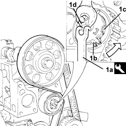
- Screw in the toothed driven pulley bolt and tighten to the recommended torque.
| Component | Fastening | dia | Value (daNm) | Validity |
|---|---|---|---|---|
| Driven toothed pulley | Bolt | M10 | 6.3 ÷ 7.7 | 1.2 8v |
- Remove both templates and the reaction tool fitted previously and turn the engine through a couple of revolutions to settle the timing belt.
- Loosen the belt tensioner nut and adjust the front fork until it is aligned with the rear fork.
- Tighten the belt tensioner nut to the recommended torque.
| Component | Fastening | dia | Value (daNm) | Validity |
|---|---|---|---|---|
| Timing moving tensioner | Nut | M8 | 2.5 ÷ 3.1 | 1.2 8v 1.4 8v |
- Fit the templates removed previously to check the engine timing adjustment.
- Position the cam cover on the cylinder head and secure it using the fixing bolts.
| Component | Fastening | dia | Value (daNm) | Validity |
|---|---|---|---|---|
| Tappet cover | Bolt | M6 | 0.8 ÷ 1.0 | 1.2 8v 1.4 8v 1.3 Multijet 1.9 Multijet |
- Fit the injection control unit mount.
- Fit the rpm sensor and tighten the bolt.
- Fit the knock sensor and tighten the bolt to the specified torque.
| Component | Fastening | dia | Value (daNm) | Validity |
|---|---|---|---|---|
| Detonation sensor | Bolt (to be replaced) | M8 | 2.2 ÷ 2.7 | 1.2 8v 1.4 8v 1.4 16v |
- Fit the engine oil dipstick tube.
- Fit the mount with compressor and alternator and secure the fastenings.
| Component | Fastening | dia | Value (daNm) | Validity |
|---|---|---|---|---|
| Compressor support | Bolt | M10x1.25 | 4.5 ÷ 5.5 | 1.2 8v |
| Component | Fastening | dia | Value (daNm) | Validity |
|---|---|---|---|---|
| Compressor support | Nut | M8x1.25 | 2.3 ÷ 2.7 | 1.2 8v |
| Component | Fastening | dia | Value (daNm) | Validity |
|---|---|---|---|---|
| Compressor support | Nut | M10x1.25 | 4.5 ÷ 5.5 | 1.2 8v |
- Fit the timing belt protective covers and secure them using the bolts.
- Fit the crankshaft pulley and tighten the bolts to the recommended torque.
| Component | Fastening | dia | Value (daNm) | Validity |
|---|---|---|---|---|
| Services pulley on crankshaft | Bolt | M8 | 2.3 ÷ 2.8 |
- Fit the auxiliary drivebelt by adjusting the automatic belt tensioner.
- Fit the timing side rigid power unit mount and tighten the bolts to the specified torque.
| Component | Fastening | dia | Value (daNm) | Validity |
|---|---|---|---|---|
| Timing side power unit rigid support | Bolt | M10 | 5.4 ÷ 6.6 | 1.2 8v 1.4 8v 1.4 16v |
- Connect the electrical connection for the coolant temperature sensor.
- Connect the electrical connection for the timing sensor.
- Connect the electrical connection of the ignition coil module.
- Connect the electrical connection for the throttle casing.
- Connect the electrical connection for the knock sensor.
- Connect the air conditioning compressor electrical connection.
- Connect the earth lead to the crankcase.
- Connect the electrical connection for the air pressure/temperature sensor.
- Remove the engine from the overhaul stand.
Removing
1. Undo the bolts (1a) and the nuts (1b) and remove the mounting (1c) complete with alternator (1d) and air conditioning compressor (1e).
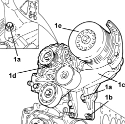
1. Undo the bolt (1a) and remove the rigid engine coolant pump inlet pipe (1b) with seal.
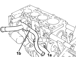
1. Undo the bolts (1a) and the nut (1b) securing the water pump to the crankcase.
2. Remove the sealant using the tool (2a) and remove the water pump (2b).
| Tool | Description | Function | Validity |
|---|---|---|---|
| 1870718000 | Blade | Cut sealant |
- Clean thoroughly between the crankcase and water pump mating surfaces.
3. Using a suitable tool remove the engine oil filter cartridge.
4. Remove the minimum engine oil pressure switch.
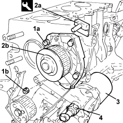
1. Undo the bolts (1a) and remove the crankcase front cover (1b) with the oil pump incorporated complete with gasket (1c) and intake (1d).
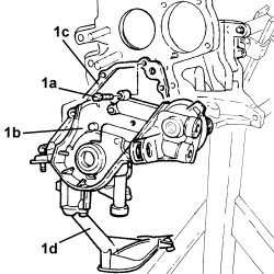
1. Fit the tool (1a) and undo the bolt (1b) securing the crankshaft gear.
| Tool | Description | Function | Validity |
|---|---|---|---|
| 2000004500 | Template | Crankshaft timing | 1.2 8v 1.4 8v 1.4 16v |
- Remove the template fitted previously.
2. Remove the crankshaft gear.
3. Undo the bolt (3a) and remove the rpm sensor (3b).
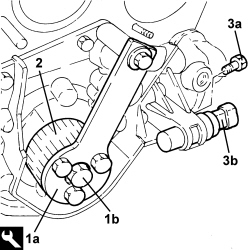
1. Undo the bolts (1a) and remove the crankshaft rear cover (1b).
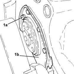
- Rotate the engine block through 180°.
1. Fit the tool for rotating the crankshaft.
| Tool | Description | Function | Validity |
|---|---|---|---|
| 1860815000 | Flange | Crankshaft rotation | 1.4 16v 1.3 Multijet |
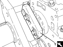
1. Undo the bolts (1a) and remove the connecting rod caps (1b).
2. Remove the lower crankpin half-bearings.
3. Remove the connecting rod - piston assemblies.
4. Remove the upper connecting rod half-bearings.
The arrow on the piston crown facing the timing side indicates the fitting direction.
The matching of the connecting rod-cap is the "BREAKING" type therefore the position is compulsory and the number corresponding to the position of the cylinder must be present.
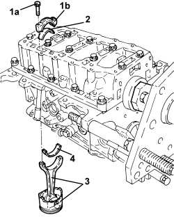
- Remove the flange for rotating the crankshaft fitted previously.
1. Using a dial gauge, check that the crankshaft endfloat is within specified limits.
| Measurement | Value | Validity |
|---|---|---|
| Crankshaft endfloat (mm) | 0.155 ÷ 0.355 | 1.4 16v |
- Remove the dial gauge.
If the value for the crankshaft endfloat does not correspond with the recommended figures, when refitting, regrind the crankcase seat and use the central main bearing half incorporating appropriately oversized crankshaft thrust half-washers.
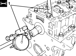
1. Undo the bolts (1a) and remove the lower crankcase (1b) complete with lower half-bearings from the engine block.
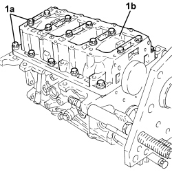
1. Remove the lower main journal half-bearings from the engine block.
2. Remove the crankshaft.
3. Remove the upper main journal half-bearings.
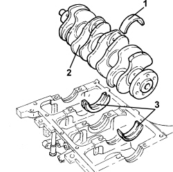
1. Undo the bolt and remove the detonation sensor.
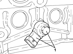
- Remove the lower engine block locating bushes.
- Raise the engine block using a hydraulic lift and place it on a suitable workbench.
Op. 1084B18 ENGINE OIL PUMP, REMOVED - CHECK AT BENCH
1. Remove the coolant chamber plugs from the crankcase using a steel drift.
2. Remove the lubrication duct plug from the crankcase using a steel drift.
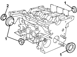
1. Remove the oil jets (1a) using the tool (1b).
| Tool | Description | Function | Validity |
|---|---|---|---|
| 1860395000 | Picker | Engine oil jet removal | 1.2 8v 1.4 8v 1.4 16v |
Insert the drift guide hole on the nozzle surface to prevent the drift from slipping and damaging the cylinder liner during the removal operation.
Use new oil jets when refitting.
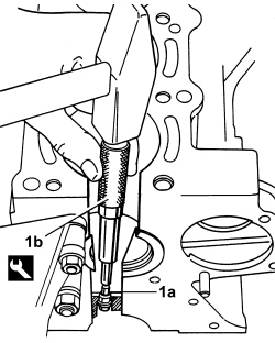
Refitting
- Wash and check the appearance of all components removed.
- Place the crankcase on the overhaul stand.
- Fit the water/oil sealing plugs in the crankcase using suitable fitting tools and sealant.
- Fit the locating bushes for the crankcase.
1. Use tool (1a) and a plastic mallet to fit the new oil sprays (1b).
| Tool | Description | Function | Validity |
|---|---|---|---|
| 1860313000 | Fitting tool | Engine oil jet fitting | 1.2 8v 1.4 8v 1.4 16v |
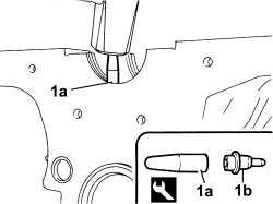
1. Using a calibrated metal rule (1a) and a feeler gauge (1b), check the planarity of the cylinder head - cylinder block/crankcase support surface.
2. If the measurement does not correspond to the recommended values, regrind the cylinder head support surface.
| Measurement | Value | Validity |
|---|---|---|
| Cylinder head support surface flatness (mm) | < 0.1 | 1.2 8v 1.4 8v 1.4 16v 1.9 Multijet |
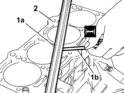
- Measure the diameter of the cylinder bores and check that they correspond to the recommended figures.
| Measurement | Value | Validity |
|---|---|---|
| Cylinder liner diameter - Grade A (mm) | 72.000 ÷ 72.010 | 1.4 8v 1.4 16v |
| Measurement | Value | Validity |
|---|---|---|
| Cylinder liner diameter - Grade B (mm) | 72.010 ÷ 72.020 | 1.4 8v 1.4 16v |
| Measurement | Value | Validity |
|---|---|---|
| Cylinder liner diameter - Grade C (mm) | 72.020 ÷ 72.030 | 1.4 8v 1.4 16v |
- Check that the ovality of the cylinder liners is within the recommended limits.
| Measurement | Value | Validity |
|---|---|---|
| Cylinder liner ovality (mm) | +/- 0.05 | 1.2 8v 1.4 8v 1.4 16v |
- Check that the taper of the cylinder liners/bores is within the recommended limits.
| Measurement | Value | Validity |
|---|---|---|
| Cylinder liner taper (mm) | +/- 0.005 | 1.2 8v 1.4 8v 1.4 16v |
- If the cylinder bore, taper or ovality measurements are not within the recommended limits, ream the cylinder bores following the recommended oversizes.
In the case of reaming, all the bores must have the same oversize.
| Measurement | Value | Validity |
|---|---|---|
| Cylinder liner diameter oversize (mm) | 0.1 | 1.2 8v 1.4 8v 1.4 16v 1.3 Multijet 1.9 Multijet |
- Check that the diameter of the main journals corresponds to the recommended figures.
| Measurement | Value | Validity |
|---|---|---|
| Main journal diameter - Category A (mm) | 47.997 ÷ 48.003 | 1.4 8v 1.4 16v |
| Measurement | Value | Validity |
|---|---|---|
| Main journal diameter - Category B (mm) | 47.988 ÷ 47.994 | 1.4 8v 1.4 16v |
| Measurement | Value | Validity |
|---|---|---|
| Main journal diameter - Category C (mm) | 47.982 ÷ 47.988 | 1.4 8v 1.4 16v |
- If the diameter of the main journals is not correct, they should be reground to the recommended undersize.
Because the crankshaft has undergone nitriding, this treatment should be repeated and the size re-checked if it is ground.
| Measurement | Value | Validity |
|---|---|---|
| Main journal diameter undersize (mm) | 0.127 | 1.2 8v 1.4 8v 1.4 16v 1.3 Multijet |
- Check that the diameter of the crankpins corresponds to the recommended figures.
| Measurement | Value | Validity |
|---|---|---|
| Crankpin diameter (mm) | 41.990 ÷ 42.008 | 1.2 8v 1.4 8v 1.4 16v |
- If the diameter of the crankpins is not correct, they should be reground to the recommended undersize.
Because the crankshaft has undergone nitriding, this treatment should be repeated and the size re-checked if it is ground.
| Measurement | Value | Validity |
|---|---|---|
| Crankpin diameter undersize (mm) | 0.127 | 1.2 8v 1.4 8v 1.4 16v 1.3 Multijet 1.9 Multijet |
- Check the main bearings, noting that the half-bearings should not be adapted. Replace them if scoring or signs of binding are noted.
- Fit the main bearing halves in their seats on the upper crankcase, aligning the lubrication holes and ensuring scrupulous cleanliness. The centre crankshaft bearing has thrust half-washers incorporated becuase it acts as a thrust carrier.
- If the crankshaft has been ground, fit new oversize half-bearings to restore the initial tolerance conditions.
1. Fit the crankshaft in the special housing in the engine block with the upper half-bearings.
2. Fit the calibrated wire (plastigage) for measuring the bearing clearance.
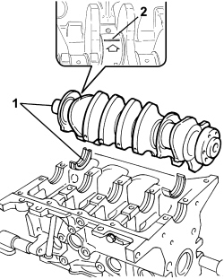
1. Fit the main journal half-bearings in the lower cylinder block/crankcase.
2. Fit the lower crankcase on the engine block checking that the codes stamped on both parts of the crankcase are aligned because the crankcase components are not interchangeable.
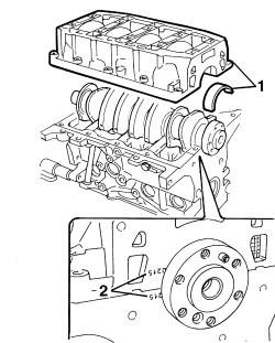
- The size of the main journal half-bearings is given.
| Measurement | Value | Validity |
|---|---|---|
| Main journal half-bearings - Category 1 (Red) (mm) | 1.836 ÷ 1.840 | 1.2 8v 1.4 8v 1.4 16v |
| Measurement | Value | Validity |
|---|---|---|
| Main journal half-bearings - Category 2 (Blue) (mm) | 1.843 ÷ 1.847 | 1.2 8v 1.4 8v 1.4 16v |
| Measurement | Value | Validity |
|---|---|---|
| Main journal half-bearings - Category 3 (Yellow) (mm) | 1.848 ÷ 1.852 | 1.2 8v 1.4 8v 1.4 16v |
| Measurement | Value | Validity |
|---|---|---|
| Main bearing half undersize (mm) | 0.127 | 1.4 16v |
- Tighten the bolts securing the lower crankcase to the engine block to the specified torque.
| Component | Fastening | dia | Value (daNm) | Validity |
|---|---|---|---|---|
| Cylinder block/crankcase | Central bolt | M10 | 1.9 ÷ 2.1 + 87° ÷ 93° | 1.4 16v |
| Component | Fastening | dia | Value (daNm) | Validity |
|---|---|---|---|---|
| Cylinder block/crankcase | Side bolt | M10 | 2.8 ÷ 3.2 | 1.4 16v |
1. Remove the lower crankcase and check the crankpin clearance. Use an appropriate gauge to measure the width of the plastigage.
Check one main journal at a time, without rotating the crankshaft.
| Measurement | Value | Validity |
|---|---|---|
| Clearance between main bearings - crankshaft main journals (mm) | 0.025 ÷ 0.040 | 1.2 8v 1.4 8v 1.4 16v |
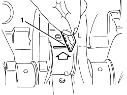
- After checking all the main journals, apply sealant to the contact surfaces between the lower crankcase and upper crankcase. Then fit the lower crankcase permanently by tightening the bolts to torque in the order described previously.
Apply a 2 mm thick sealant strip continuously to the lower crankcase surface.
- Check that the outer diameter of the pistons corresponds to the recommended figures; if not, replace the pistons complete with piston rings and gudgeon pins.
| Measurement | Value | Validity |
|---|---|---|
| Piston outer diameter -Grade A (mm) | 71.960 ÷ 71.970 | 1.4 8v 1.4 16v |
| Measurement | Value | Validity |
|---|---|---|
| Piston outer diameter - Grade B (mm) | 71.970 ÷ 71.980 | 1.4 8v 1.4 16v |
| Measurement | Value | Validity |
|---|---|---|
| Piston outer diameter - Grade C (mm) | 71.980 ÷ 71.990 | 1.4 8v 1.4 16v |
Measure perpendicular to the gudgeon pin axis, 9 mm from the lower edge of the skirt.
- Position the pistons in the cylinder liners/bores and use a feeler gauge to measure the specified clearance.
| Measurement | Value | Validity |
|---|---|---|
| Clearance between piston - cylinder liner/bore (mm) | 0.030 ÷ 0.050 | 1.4 16v |
- Check that the inner bore of the gudgeon pin housings is within the recommended limits; if not, replace the pistons.
| Measurement | Value | Validity |
|---|---|---|
| Piston pin housing diameter (mm) | 17.982 ÷ 17.986 | 1.4 16v |
- Check that the outer diameter of the gudgeon pins is within the recommended limits; if not, replace the worn gudgeon pins.
| Measurement | Value | Validity |
|---|---|---|
| Piston pin outer diameter (mm) | 17.970 ÷ 17.974 | 1.2 8v 1.4 8v 1.4 16v |
- Use a micrometer gauge to measure the thickness of the piston rings.
| Measurement | Value | Validity |
|---|---|---|
| Cylinder compression 1st piston ring thickness (mm) | 0.970 ÷ 0.990 | 1.4 8v 1.4 16v |
| Measurement | Value | Validity |
|---|---|---|
| Cylinder compression 2nd piston ring thickness (mm) | 1.170 ÷ 1.190 | 1.4 8v 1.4 16v |
| Measurement | Value | Validity |
|---|---|---|
| Cylinder compression 3rd piston ring thickness (mm) | 1.975 ÷ 1.990 | 1.4 8v 1.4 16v |
| Measurement | Value | Validity |
|---|---|---|
| Seal oversize (mm) | 0.1 | 1.2 8v 1.4 8v 1.4 16v |
1. Fit the sealing rings (1a) in the cylinder liners/bores and use a feeler gauge (1b) to check the gap between the seal ends is within specified limits. Otherwise replace the sealing rings.
| Measurement | Value | Validity |
|---|---|---|
| Cylinder compression 1st piston ring gap (mm) | 0.20 ÷ 0.40 | 1.4 16v |
| Measurement | Value | Validity |
|---|---|---|
| Cylinder compression 2nd piston ring gap (mm) | 0.25 ÷ 0.45 | 1.4 16v |
| Measurement | Value | Validity |
|---|---|---|
| Cylinder compression 3rd piston ring gap (mm) | 0.20 ÷ 0.40 | 1.4 16v |
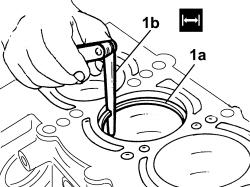
- Check that the piston ring seats are within the recommended values.
| Measurement | Value | Validity |
|---|---|---|
| Piston ring seat in piston - 1st groove (mm) | 1.020 ÷ 1.040 | 1.4 8v 1.4 16v |
| Measurement | Value | Validity |
|---|---|---|
| Piston ring seat in piston - 2nd groove (mm) | 1.210 ÷ 1.230 | 1.4 8v 1.4 16v |
| Measurement | Value | Validity |
|---|---|---|
| Piston ring seat in piston - 3rd groove (mm) | 2.010 ÷ 2.030 | 1.4 8v 1.4 16v |
1. Use a feeler gauge (1a) to check the mating clearance between the retaining rings (1b) and the grooves on the pistons (1c).
| Measurement | Value | Validity |
|---|---|---|
| Cylinder compression 1st piston ring endfloat (mm) | 0.030 ÷ 0.070 | 1.4 8v 1.4 16v |
| Measurement | Value | Validity |
|---|---|---|
| Cylinder compression 2nd piston ring endfloat (mm) | 0.020 ÷ 0.060 | 1.4 8v 1.4 16v |
| Measurement | Value | Validity |
|---|---|---|
| Cylinder compression 3rd piston ring endfloat (mm) | 0.020 ÷ 0.055 | 1.4 8v 1.4 16v |
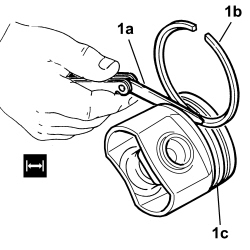
- Check that the diameter of the big ends and the small ends are within the recommended values.
| Measurement | Value | Validity |
|---|---|---|
| Big end diameter (mm) | 45.128 ÷ 45.138 | 1.4 16v |
| Measurement | Value | Validity |
|---|---|---|
| Small end diameter (mm) | 17.939 ÷ 17.956 | 1.4 16v |
Op. 1084B18 ENGINE OIL PUMP, REMOVED - CHECK AT BENCH
- Fit the tool for rotating the crankshaft.
| Tool | Description | Function | Validity |
|---|---|---|---|
| 1860815000 | Flange | Crankshaft rotation | 1.4 16v 1.3 Multijet |
- Fit the connecting rod-piston assemblies and align in accordance with the following references.
1. Piston class and arrow indicating timing side.
2. Area where the number of the matching cylinder liner is stamped.
3. Gudgeon pin offset
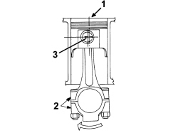
The matching of the connecting rod-cap is the "BREAKING" type therefore the position is compulsory and the number corresponding to the position of the cylinder must be present.
Letters identifying the cylinder liner classes are shown on the crankcase.
1. Fit the connecting rod-piston assemblies (1a) with half-bearings using tool the (1b) to compress the piston rings and then fit the piston into the liner/bore.
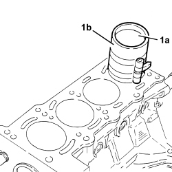
- Rotate the engine on the overhaul stand.
1. Apply the calibrated wire (plastigate) for measuring the crankpin clearance.
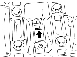
- The size of the connecting rod half-bearings is given.
| Measurement | Value | Validity |
|---|---|---|
| Connecting rod half-bearing thickness (mm) | 1.544 ÷ 1.548 | 1.2 8v 1.4 8v 1.4 16v |
- Refit the connecting rod caps complete with half-bearings and secure them by tightening the bolts to the recommended torque.
The connecting rod caps are fracture type. If replaced, they are supplied pre-fractured by the manufacturer. Check that the parts are free of burrs, blisters, scratches or any other surface defect. Before installation, parts must be thorougly washed, cleaned and dried. Fit the connecting rod caps so that the number stamped on each cap faces towards the same side as the number stamped on the big end.
Each connecting rod must be paired with its cap, respecting the numerical references stamped on the parts. Connecting rods and connecting rod caps are not interchangeable.
| Component | Fastening | dia | Value (daNm) | Validity |
|---|---|---|---|---|
| Connecting rod big end bearing caps | Bolt | M8 | 1.9 ÷ 2.1 + 40° +/- 2° | 1.2 8v 1.4 8v 1.4 16v 1.3 Multijet |
1. Remove the connecting rod caps and check the crankpin clearance. Use an appropriate gauge to measure the width of the plastigage.
Check one crankpin at a time, without rotating the crankshaft.
| Measurement | Value | Validity |
|---|---|---|
| Clearance between connectring rod bearings - crankpins (mm) | 0.023 ÷ 0.060 | 1.4 16v |
- If the value measured is not within the recommended figures, replace the connecting rod bearings.
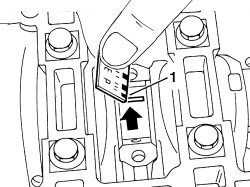
- Refit the connecting rod caps complete with half-bearings and secure them by tightening the bolts to the torque given previously.
- Rotate the engine on the overhaul stand.
- Position a new oil pump gasket.
- Fit the front crankcase cover with built-in oil pump complete with intake chamber and secure by tightening bolts to the specified torque.
| Component | Fastening | dia | Value (daNm) | Validity |
|---|---|---|---|---|
| Engine oil pump | Bolt | M6 | 0.9 ÷ 1.1 | 1.4 16v |
- Place the engine oil filter in its housing.
- Place the minimum engine oil pressure switch in position and tighten it to the recommended torque.
| Component | Fastening | dia | Value (daNm) | Validity |
|---|---|---|---|---|
| Switch for engine oil pressure warning light | M14 | 2.9 ÷ 3.5 |
- Fit the oil seal on the crankshaft front cover using the tool.
| Tool | Description | Function | Validity |
|---|---|---|---|
| 1860990000 | Fitting tool | Fitting crankshaft front cover oil seal Fitting oil seal on exhaust camshaft | 1.2 8v 1.4 8v 1.4 16v |
- Remove the flange for rotating the crankshaft fitted previously.
- Place the crankcase rear cover in position and secure it tightening the bolts to the recommended torque.
| Component | Fastening | dia | Value (daNm) | Validity |
|---|---|---|---|---|
| Crankshaft to crankcase rear cover | Bolt | M6 | 0.8 ÷ 1.0 | 1.2 8v 1.4 8v 1.4 16v |
- Place the crankshaft gear in its housing.
1. Because the timing is adjusted with the four pistons in line, i.e. half-way along their effective strokes, it is essential to position the crankshaft in phase with the camshafts. They can be approximately positioned by turning the crankshaft gear (1a) until the locating dowel (1b) is positioned opposite to the rpm sensor seat (1c) with the first cylinder piston in descending phase, i.e. intake.
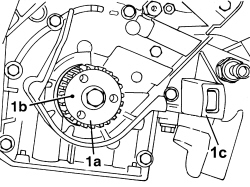
1. Position the counter-torque tool.
| Tool | Description | Function | Validity |
|---|---|---|---|
| 2000004500 | Template | Crankshaft timing | 1.2 8v 1.4 8v 1.4 16v |
2. Secure the crankshaft gear (2a) by tightening the bolt (2b) to the specified torque.
| Component | Fastening | dia | Value (daNm) | Validity |
|---|---|---|---|---|
| Crankshaft gear | Bolt | M12 | 1.9 ÷ 2.1 + 107° ÷ 113° | 1.4 16v |
3. Position the rpm sensor (3a) in its housing and secure it tightening the bolt (3b) to the recommended torque.
| Component | Fastening | dia | Value (daNm) | Validity |
|---|---|---|---|---|
| Rpm sensor | Bolt | M6 | 0.8 ÷ 1.0 | 1.2 8v 1.4 8v 1.4 16v |
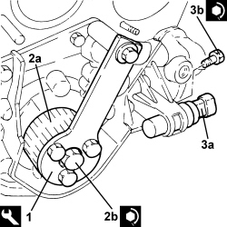
- Apply silicon sealant to the outer edge of the water pump.
- Position the water pump in its housing and secure it tightening the bolts and the nut to the recommended torque.
| Component | Fastening | dia | Value (daNm) | Validity |
|---|---|---|---|---|
| Water pump | Bolt | M6 | 0.9 ÷ 1.1 | 1.4 16v |
| Component | Fastening | dia | Value (daNm) | Validity |
|---|---|---|---|---|
| Water pump | Nut | M6 | 0.9 ÷ 1.1 | 1.4 16v |
- Place the water pump rigid inlet pipe, complete with new gasket, in position and secure it tightening the bolt to the recommended torque.
| Component | Fastening | dia | Value (daNm) | Validity |
|---|---|---|---|---|
| Water pump rigid inlet pipe | Bolt | M6 | 0.9 ÷ 1.1 | 1.4 16v |
- Rotate the engine through 180° on the overhaul stand.
- Clean the crankcase and oil sump contact surfaces, removing the silicon sealant residues.
- Apply the sealant without a break to the entire perimeter of the oil sump.
- Position the oil sump in its housing and secure it tightening the bolts and the nuts to the recommended torque.
When positioning the oil sump, avoid significant sideways movements that could remove the sealant.
| Component | Fastening | dia | Value (daNm) | Validity |
|---|---|---|---|---|
| Engine oil sump | Bolt | M6 | 0.8 ÷ 1.0 | 1.4 16v |
| Component | Fastening | dia | Value (daNm) | Validity |
|---|---|---|---|---|
| Engine oil sump | Nut | M6 | 0.8 ÷ 1.0 | 1.4 16v |
- Rotate the engine through 180° on the overhaul stand.
- Fit the locating dowels in the crankcase.
- Fit a new left cylinder head gasket on the cylinder block.
- Position the cylinder head on the crankcase by aligning the locating pins.
1. Tighten the bolts securing the cylinder head to the recommended torque.
Follow the order shown in the figure for each tightening sequence.
| Component | Fastening | dia | Value (daNm) | Validity |
|---|---|---|---|---|
| Cylinder head | Bolt | M9 | 3 + 90° + 90° | 1.4 16v |
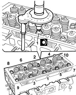
- Fit the locating dowels and position the camshaft housing gasket on the cylinder head support plane.
- Position the tappet retaining tools beneath the camshaft housing, then place the camshaft housing on the cylinder head and withdraw the tools.
- Use the tool to tighten the camshaft housing bolts to the specified torque.
| Tool | Description | Function | Validity |
|---|---|---|---|
| 1860834000 | Spanner | Loosen/tighten the camshaft housing bolts | 1.4 16v |
| Component | Fastening | dia | Value (daNm) | Validity |
|---|---|---|---|---|
| Engine camshaft housing | Bolt | M8 | 1.3 ÷ 1.6 | 1.4 16v |
- Refit the plugs complete with new O-rings and tighten them to the recommended torque.
| Component | Fastening | dia | Value (daNm) | Validity |
|---|---|---|---|---|
| Camshaft housing plugs | M16 | 1.3 ÷ 1.6 | 1.4 16v |
- Place the thermostat in its housing with the new O-ring and secure it by tightening the bolts to the recommended torque.
| Component | Fastening | dia | Value (daNm) | Validity |
|---|---|---|---|---|
| Thermostat | Bolt | M6 | 0.9 ÷ 1.1 | 1.4 16v |
- Place the timing belt moving tensioner in its housing without tightening the nut.
- Place the driven pulley/phase transformer in its housing.
- Fit the driven pulley/phase transformer locking tool.
| Tool | Description | Function | Validity |
|---|---|---|---|
| 2000015800 | Counter-torque | Locking driven pulley/phase transformer | 1.4 16v |
- Tighten the driven pulley/phase transformer fixing bolt to the specified torque.
| Component | Fastening | dia | Value (daNm) | Validity |
|---|---|---|---|---|
| Driven pulley/phase transformer | Bolt | M8 | 1.9 ÷ 2.1 + 55° +/- 2° | 1.4 16v |
- Tighten the camshaft idler gears fixing bolts to the recommended torque.
| Component | Fastening | dia | Value (daNm) | Validity |
|---|---|---|---|---|
| Camshaft gears | Bolt | M12 | 12.0 | 1.4 16v |
- Loosen the bolt securing the driven pulley/phase transformer and remove the locking tool.
- Remove the tool used previously for counter-torque for tightening the bolt securing the crankshaft gear.
| Tool | Description | Function | Validity |
|---|---|---|---|
| 2000004500 | Template | Crankshaft timing | 1.2 8v 1.4 8v 1.4 16v |
1. Position the tools (1a) in their seats for the spark plug for the 1st and 2nd cylinder tightening the pins (1b) to a torque of 0.5 daNm.
| Tool | Description | Function | Validity |
|---|---|---|---|
| 1860992000 | Bearings | Crankshaft timing | 1.4 16v |
2. Rotate the crankshaft in its normal direction of rotation until the tool moving pins fitted previously are aligned with one another.
Rotate the crankshaft proceeding gradually to prevent the tool pins being expelled by the compression of the pistons.
3. The camshaft timing was adjusted previously by fitting the tools illustrated.
| Tool | Description | Function | Validity |
|---|---|---|---|
| 1860985000 | Locating pins. | Camshaft timing | 1.4 16v |
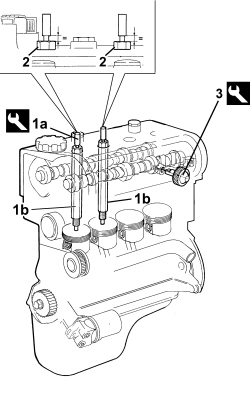
- Proceed with fitting the timing drive belt, firstly fitting it on the crankshaft gear, the water pump pulley, the driven pulley/phase transformer and lastly on the moving tensioner.
Ensure that this operation is performed with the driven pulley/phase transforer slack.
1. Tension the timing belt by turning it anticlockwise with the tool (1a) and the moving tensioner (1b) and then secure it when the reference fork (1c) is in contact (1d).
| Tool | Description | Function | Validity |
|---|---|---|---|
| 1860987000 | Spanner | Tensioning toothed timing drive belt | 1.2 8v 1.4 8v 1.4 16v |
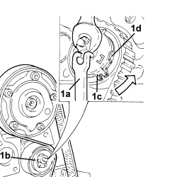
- Fit the driven pulley/phase transformer locking tool.
| Tool | Description | Function | Validity |
|---|---|---|---|
| 2000015800 | Counter-torque | Locking driven pulley/phase transformer | 1.4 16v |
- Tighten the driven pulley/phase transformer fixing bolt to the specified torque.
| Component | Fastening | dia | Value (daNm) | Validity |
|---|---|---|---|---|
| Driven pulley/phase transformer | Bolt | M8 | 1.9 ÷ 2.1 + 55° +/- 2° | 1.4 16v |
- Place the driven pulley/phase transformer sealing plug in position and tighten it to the recommended torque.
| Component | Fastening | dia | Value (daNm) | Validity |
|---|---|---|---|---|
| Driven pulley/phase transformer sealing plug | Plug | M27 | 2.7 ÷ 3.3 | 1.4 16v |
- Remove the tools positioned previously for the timing and locking of the camshafts and rotate the crankshaft through two revolutions.
1. Loosen the moving tensioner nut and adjust the front fork using the tool (1a) until it is aligned with the rear fork (1b).
2. Tighten the nut fixing the moving tensioner to the recommended torque.
| Component | Fastening | dia | Value (daNm) | Validity |
|---|---|---|---|---|
| Timing moving tensioner | Nut | M8 | 2.2 ÷ 2.7 | 1.4 16v |
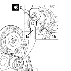
- Turn the crankshaft through two revolutions in its normal rotation direction, then reposition the tools used to adjust engine timing and check the engine is in phase.
- Remove the tools used for timing the engine.
- Place the side plugs in their seats in the camshaft housing and tighten them to the recommended torque.
| Component | Fastening | dia | Value (daNm) | Validity |
|---|---|---|---|---|
| Camshaft housing plugs | M16 | 1.3 ÷ 1.6 | 1.4 16v |
- Place the flywheel side camshaft rear cover in its housing and secure it using the nuts.
- Position the timing sensor in its housing and secure it using the bolt.
- Place the connector holder bracket back in its housing.
- Place the timing belt inner guard in its housing and secure it using the bolt.
- Place the oil vapour separator in its housing and secure it using the bolts and the nut.
- Fit the spark plugs and tighten them to the recommended torque.
| Component | Fastening | dia | Value (daNm) | Validity |
|---|---|---|---|---|
| Spark plugs | M12 | 1.6 ÷ 2.0 | 1.4 16v |
- Fit the ignition coils and tighten them to the recommended torque.
| Component | Fastening | dia | Value (daNm) | Validity |
|---|---|---|---|---|
| Ignition coils | Bolt | M6 | 0.8 ÷ 1.0 | 1.2 8v 1.4 8v 1.4 16v |
- Place the intake manifold on the cylinder head and secure it tightening the bolts to the recommended torque.
| Component | Fastening | dia | Value (daNm) | Validity |
|---|---|---|---|---|
| Intake manifold - cylinder head side | Bolt (to be replaced) | M7 | 1.3 ÷ 1.6 | 1.4 16v |
- Connect the pipe to the oil vapour separator and secure it using the band.
- Place the engine oil dipstick pipe back in its housing and fasten it with the bolt.
- Fit the upper and lower timing drive belt covers and secure them using the bolts.
- Place the timing side rigid engine support in position and secure it tightening the bolts to the recommended torque.
| Component | Fastening | dia | Value (daNm) | Validity |
|---|---|---|---|---|
| Rigid engine support, timing side | Bolt | M8 | 2.2 ÷ 2.7 | 1.4 16v |
- Position the detonation sensor in its housing and secure it tightening the bolt to the recommended torque.
| Component | Fastening | dia | Value (daNm) | Validity |
|---|---|---|---|---|
| Detonation sensor | Bolt (to be replaced) | M8 | 2.2 ÷ 2.7 | 1.2 8v 1.4 8v 1.4 16v |
- Place the mounting complete with alternator and air conditioning compressor in position and secure it tightening the nuts and bolts to the recommended torque.
| Component | Fastening | dia | Value (daNm) | Validity |
|---|---|---|---|---|
| Air conditioning compressor/alternator mounting | Bolt | M10 | 4.5 ÷ 5.5 | 1.4 16v |
- Position the crankshaft pulley in its housing and secure it tightening the bolts to the recommended torque.
| Component | Fastening | dia | Value (daNm) | Validity |
|---|---|---|---|---|
| Services pulley on crankshaft | Bolt | M8 | 2.3 ÷ 2.8 |
- Fit the auxiliary drivebelt.
- Place the phase transformer solenoid guard back in its housing and secure it using the bolts.
- Connect the engine block earth lead and tighten the bolt.
- Connect the alternator earth lead and tighten the nut.
- Connect the electrical connection for the slider solenoid valve.
- Connect the electrical connection for the air conditioning compressor engagement solenoid valve.
- Connect the electrical connection for the detonation sensor.
- Connect the injector wiring junction.
- Connect the electrical connection for the fuel vapour recovery solenoid valve.
- Connect the electrical connection for the slider position sensor.
- Connect the electrical connection for the throttle casing.
- Connect the electrical connection for the timing sensor.
- Connect the electrical connection for the coolant temperature sensor.
- Connect the electrical connections for the ignition coils.
- Connect the electrical connection for the absolute pressure sensor.
- Connect the earth lead and tighten the bolt.
- Connect the electrical connection for the air pressure/temperature sensor.
- Connect the electrical connection for the phase transformer actuator.
- Connect the electrical connection for the rpm sensor.
- Connect the electrical connection for the engine oil pressure switch.
- Fasten the cable loom retaining duct to the camshaft housing and attach the intermediate retaining clips.
Parts & tools for this job For 2005 Fiat Grande Punto
- PARTEngine gasket setSearch: Fiat Grande Punto 2005 engine gasket set
- TOOLTorque wrenchSearch: 3/8 inch torque wrench
- TOOLFeeler gauge setSearch: feeler gauge set
Links open Amazon search results in a new tab. As an Amazon Associate I earn from qualifying purchases.