
Power unit with manual gearbox - r.r
- Make
- Fiat
- Model
- Grande Punto Factory Service Manual
- Year
- 2005–2012
- Section
- Engine and power unit › Power unit with manual gearbox - r.r
POWER UNIT WITH MANUAL GEARBOX - R.R
Removing
Op. 5530B52 BATTERY SUPPORT/DRIP TRAY - R.R
Op. 1048A23 COLD AIR INTAKE FOR AIR FILTER - R.R
Op. 1048A10 AIR FILTER ASSEMBLY - R.R.
Op. 0010T84 COOLANT FOR AIR CONDITIONING SYSTEM - DEHYDRATE AND REPRESSURIZE
Op. 7055B66 ENGINE COMPARTMENT DUST COVER IN RIGHT FRONT WHEEL ARCH - R.R.
Op. 0010T20 ENGINE COOLANT - CHANGE
Op. 0010T40 CHANGE MANUAL GEARBOX OIL
Op. 4410D17 REINFORCEMENT FOR FRONT SUSPENSION CROSSMEMBER - R.R.
Op. 1008C32 GEARBOX LOWER REACTION ROD -R.R.
Op. 4450B12 FRONT WHEELS (TWO) - R+R
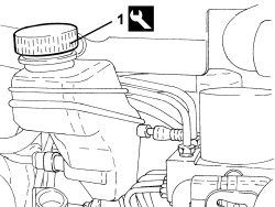
1. Undo the brake/clutch fluid reservoir cap and tighten the tool.
| Tool | Description | Function | Validity |
|---|---|---|---|
| 2000001400 | Plug | Brake/ clutch system vacuum |
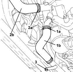
1. Loosen the band (1a) and disconnect the heat exchanger flexible air supply pipe (1b).
2. Loosen the band (2a) and disconnect the throttle casing flexible air supply pipe (2b).
3. Undo the bolt fixing the heat exchanger rigid air supply pipe to the front end.
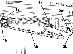
1. Undo the bolt (1a) fixing the heat exchanger rigid air inlet pipe (1b) to the front end.
2. Undo the bolt (2a) fixing the throttle casing rigid air supply pipe (2b) to the front end.
3. Undo the bolts (3a) and remove the air-air heat exchanger assembly (3b).
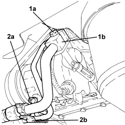
1. Undo the bolt (1a) fixing the flange for the air conditioning compressor inlet and supply pipes (1b).
2. Undo the bolt (2a) fixing the air conditioning compressor and inlet and supply pipes bracket (2b).
- Move the pipes disconnected previously aside and secure them appropriately.
1. Disconnect the rapid connector for the radiator lower coolant outlet pipe.
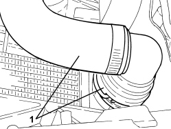
Op. 1008A45 GEARBOX SIDE RIGID SUPPORT REINFORCEMENT
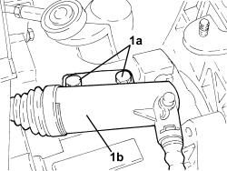
1. Undo the bolts (1a) securing the clutch control actuator (1b) to the gearbox.
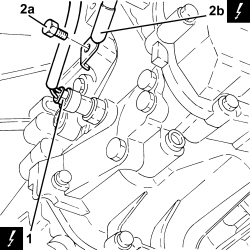
1. Disconnect the electrical connection from the reversing light switch.
| Description | Connector | |
|---|---|---|
| 1 | Reversing lights switch | See I020 REVERSING LIGHTS SWITCH |
2. Undo the bolt (2a) and disconnect the battery earth lead (2b) from the gearbox.
| Description | Connector | |
|---|---|---|
| 2b | Battery earth | See C001 BATTERY EARTH |
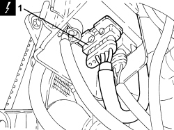
1. Disconnect the electrical connection for the heater plugs control unit.
| Description | Connector | |
|---|---|---|
| 1 | Heater plugs control unit | See M015 PLUG PREHEATING CONTROL UNIT |
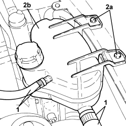
1. Loosen the bands and disconnect the pipes from the engine coolant reservoir.
2. Undo the bolts (2a) and remove the engine coolant reservoir (2b).
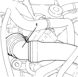
1. Disconnect the rapid connector for the radiator upper coolant inlet pipe.
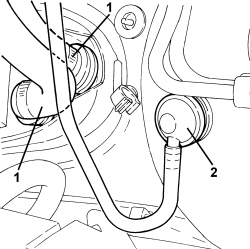
1. Disconnect the rapid connectors for the heater supply and return pipes.
2. Disconnect the single-acting valve from the brake servo.
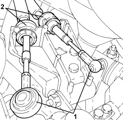
1. Disconnect the gear selector and engagement cables.
2. Retract the cursor and disconnect the gear selector and engagement cables from the bracket.
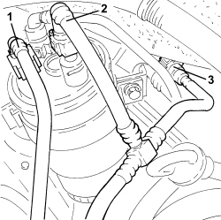
1. Disconnect the rapid connector for the front supply pipe to the pressure pump from the fuel filter.
2. Disconnect the connector for the return pipe to the fuel tank from the excess pressure valve.
3. Disconnect the intermediate rapid connector for the return pipe to the fuel tank.
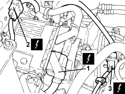
1. Connect the electrical connection for the injection control unit.
| Description | Connector | |
|---|---|---|
| 1 | Engine management control unit | See M010 ENGINE MANAGEMENT ECU |
2. Disconnect the engine coupling.
| Description | Connector | |
|---|---|---|
| 2 | Engine cables/engine services cable coupling | See D029 ENGINE CABLES/ENGINE SERVICES CABLE COUPLING |
3. Disconnect the electrical connection for the Lambda sensor.
| Description | Connector | |
|---|---|---|
| 3 | Lambda sensor on catalyzer | See K017 LAMBDA SENSOR ON CATALYZER |
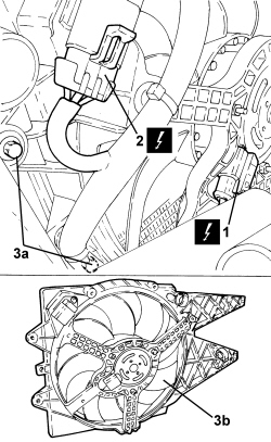
1. Disconnect the electrical connection for the fan.
| Description | Connector | |
|---|---|---|
| 1 | Engine fan motor | See N011 FAN MOTOR |
2. Disconnect the resistor electrical connection.
| Description | Connector | |
|---|---|---|
| 2 | Engine fan adjustment resistance | See O010 ENGINE FAN ADJUSTMENT RESISTANCE - 1 |
3. Undo the bolts (3a) and remove the fan (3b) from the side clips.
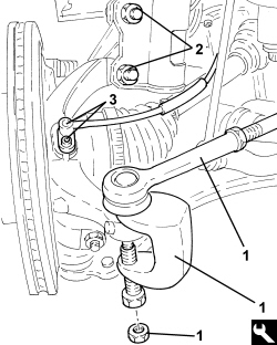
1. Unscrew the nut, fit the tool and disconnect the left steering link from the knuckle.
| Tool | Description | Function | Validity |
|---|---|---|---|
| 1871000700 | Extractor | Extracting steering rod from steering knuckle |
2. Undo the bolts securing the left front shock absorber to the knuckle.
3. Undo the bolt and remove the ABS sensor.
- Move back the left half-axle from the differential.
- Proceed in the same way for the right side.
1. Undo the bolts (1a) securing the intermediate driveshaft support (1b).
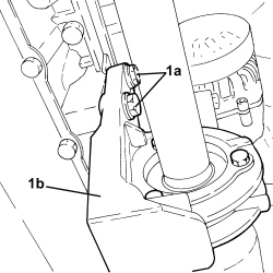
- Withdraw the right half-axle complete with intermediate driveshaft from the differential and secure to the steering box.
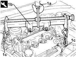
1. Support the power unit using a hydraulic hoist (1a) and the tool (1b) connected to the mounting brackets (1c) on the engine.
| Tool | Description | Function | Validity |
|---|---|---|---|
| 1871001700 | Balance | Removing/ refitting power unit |
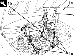
- Postion a suitable footboard beneath the power unit.
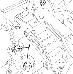
1. Undo the bolts fixing the flexible mounting to the timing side rigid power unit support.
1. Undo the bolts fixing the flexible mounting to the gearbox side rigid power unit support.
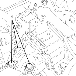
- Slowly lower the power unit with the hydraulic hoist until it rests on the board positioned previously.
Refitting
- Fit the support tools to the power unit.
- Place the power unit in its housing using the hydraulic hoist.
- Tighten the bolts fixing the flexible mounting to the gearbox side rigid power unit support to the recommended torque.
| Component | Fastening | dia | Value (daNm) | Validity |
|---|---|---|---|---|
| Gearbox side support flexible mounting to rigid support | Bolt | M12 | 9.5 ÷ 10.5 | 1.2 8v 1.4 8v 1.4 16v 1.3 Multijet |
- Tighten the bolts fixing the flexible mounting to the timing side rigid power unit support.
| Component | Fastening | dia | Value (daNm) | Validity |
|---|---|---|---|---|
| Timing side power unit to rigid support flexible mounting | Bolt | M12 | 9.0 ÷ 11.0 | 1.3 Multijet 1.9 Multijet |
- Remove the hydraulic hoist and tool used for supporting the power unit.
- Place the left half-axle back in its housing.
- Tighten the new bolts fixing the left front shock absorber to the steering knuckle to the recommended torque.
To tighten to torque, position the torque wrench on the nut and not on the bolt.
| Component | Fastening | dia | Value (daNm) | Validity |
|---|---|---|---|---|
| Front shock absorber - steering knuckle side | Bolt (to be replaced) | M12 | 10.3 ÷ 12.6 + 45° |
- Connect the left steering links to the knuckle and tighten the nut to the specified torque.
| Component | Fastening | dia | Value (daNm) | Validity |
|---|---|---|---|---|
| Steering rod to steering knuckle | Nut | M10 | 3.6 ÷ 4.4 |
- Connect the ABS sensor to the knuckle and secure it using the bolt.
- Proceed in the same way for the right side.
- Tighten the bolts fixing the intermediate driveshaft support to the cylinder block/crankcase to the recommended torque.
| Component | Fastening | dia | Value (daNm) | Validity |
|---|---|---|---|---|
| Intermediate driveshaft bearing support | Bolt | M8 | 2.0 ÷ 2.4 | 1.3 Multijet |
- Place the fan in its housing and secure it using the bolts.
- Connect the resistor electrical connection.
- Connect the electrical connection for the fan.
- Connect the electrical connection for the Lambda sensor.
- Connect the engine coupling.
- Connect the electrical connection for the injection control unit.
- Connect the intermediate rapid connector for the return pipe to the fuel tank.
- Connect the fuel supply pipe rapid connector to the fuel filter.
- Connect the return pipe to the tank to the excess pressure valve on the filter.
- Introduce the two quick-fits for hoses in the openings in the bracket keeping the cursors retracted and inserting them fully into the seats using manual pressure; release the cursors.
- Connect the ends of the gear selection-engagement cables to the ends of the gear lever.
- Connect the single-acting valve to the brake servo.
- Connect the rapid connectors for the heater supply and return pipes.
- Connect the rapid connector for the radiator upper coolant inlet pipe.
- Fit the engine cooling reservoir in place and secure it using the bolts.
- Connect the pipes to the engine coolant reservoir.
- Connect the electrical connection for the heater plugs control unit.
- Place the clutch control actuator in its housing and secure it using the bolts.
Op. 1008A45 GEARBOX SIDE RIGID SUPPORT REINFORCEMENT
- Place the battery earth lead in its housing on the gearbox and secure it using the bolt.
- Connect the electrical connection for the reversing light switch.
- Connect the rapid connector for the lower coolant outlet pipe to the radiator.
- Tighten the bolt fixing the air conditioning compressor and the inlet and supply pipe bracket to the recommended torque.
| Component | Fastening | dia | Value (daNm) | Validity |
|---|---|---|---|---|
| Compressor | Bolt | M8x1.25x80 | 2.0 ÷ 2.4 | 1.3 Multijet |
- Tighten the bolt for the connector for the air conditioning compressor inlet and supply pipes to the recommended torque.
| Component | Fastening | dia | Value (daNm) | Validity |
|---|---|---|---|---|
| Pipe connector on compressor | Bolt | M8 | 1.8 ÷ 2.2 | 1.3 Multijet 1.9 Multijet |
- Place the air/air heat exchanger assembly in its housing and secure it using the bolts.
- Tighten the bolt fixing the throttle casing rigid air supply pipe to the front end.
- Tighten the bolt fixing the heat exchanger rigid air inlet pipe to the front end.
- Tighten the bolt fixing the heat exchanger rigid air supply pipe to the front end.
- Connect the flexible air supply pipe to the throttle casing.
- Connect the flexible air supply pipe to the heat exchanger.
Op. 4450B12 FRONT WHEELS (TWO) - R+R
Op. 1008C32 GEARBOX LOWER REACTION ROD -R.R.
Op. 4410D17 REINFORCEMENT FOR FRONT SUSPENSION CROSSMEMBER - R.R.
Op. 7055B66 ENGINE COMPARTMENT DUST COVER IN RIGHT FRONT WHEEL ARCH - R.R.
Op. 1048A10 AIR FILTER ASSEMBLY - R.R.
Op. 1048A23 COLD AIR INTAKE FOR AIR FILTER - R.R
Op. 5530B52 BATTERY SUPPORT/DRIP TRAY - R.R
Op. 0010T40 CHANGE MANUAL GEARBOX OIL
Op. 0010T20 ENGINE COOLANT - CHANGE
Op. 0010T84 COOLANT FOR AIR CONDITIONING SYSTEM - DEHYDRATE AND REPRESSURIZE
Removing
- Position the vehicle on a lift.
Op. 5530B52 BATTERY SUPPORT/DRIP TRAY - R.R
Op. 1016A10 SOUND-PROOFING COVER - R.R
Op. 1048A10 AIR FILTER ASSEMBLY - R.R.
Op. 0010T84 COOLANT FOR AIR CONDITIONING SYSTEM - DEHYDRATE AND REPRESSURIZE
Op. 7055B54 UNDER ENGINE PROTECTION/GUARD - R.R.
Op. 0010T20 ENGINE COOLANT - CHANGE
Op. 0010T40 CHANGE MANUAL GEARBOX OIL
Op. 4410D17 REINFORCEMENT FOR FRONT SUSPENSION CROSSMEMBER - R.R.
Op. 1076B72 INTERMEDIATE EXHAUST PIPE WITH HOSE SECTION - R+R
Op. 1008C32 GEARBOX LOWER REACTION ROD -R.R.
Op. 4450B12 FRONT WHEELS (TWO) - R+R
Op. 7210A18 R.R FRONT CROSSMEMBER
Op. 5540B07 LEFT FRONT HEADLAMP - R.R
Op. 5540B08 RIGHT FRONT HEADLAMP - R.R
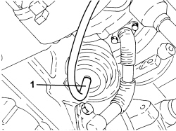
1. Disconnect the vacuum pipe from the turbocharger actuator.
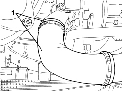
1. Loosen the band and disconnect the turbocharger air outlet hose.
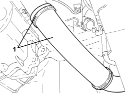
1. Loosen the band and disconnect the intercooler air outlet hose.
1. Disconnect the electrical connection for the multi-stage valve.
| Description | Connector | |
|---|---|---|
| 1 | Linear sensor for fans | See K120 LINEAR SENSOR FOR FANS |
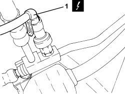
1. Disconnect the electrical connections from the engine compartment junction unit.
| Description | Connector | |
|---|---|---|
| 1 | Engine compartment junction unit | See B001 JUNCTION UNIT |
2. Disconnect the rear dashboard junctions.
| Description | Connector | |
|---|---|---|
| 2 | Rear junction/crossmember | See D106 REAR/CROSSMEMBER COUPLING |
| Description | Connector | |
|---|---|---|
| 2 | Rear dashboard/engine service junction | See D107 DASHBOARD-REAR/ENGINE SERVICES COUPLING |
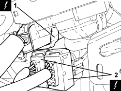
1. Undo the nut and disconnect the earth lead from the bodyshell.
| Description | Connector | |
|---|---|---|
| 1 | Battery earth on bodyshell | See C003 BATTERY EARTH ON BODYSHELL |
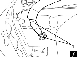
1. Disconnect the bonnet opening cable from the lock.
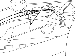
1. Loosen the collar and disconnect the sleeve from the coolant return pipe to the water pump.
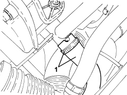
1. Loosen the band and disconnect the coolant hose from the thermostat.
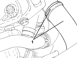
1. Loosen the band and disconnect the degassing pipe from the expansion tank.
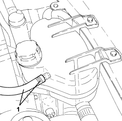
1. Unscrew the bolts (1a) and remove the wing union assembly ring (1b).
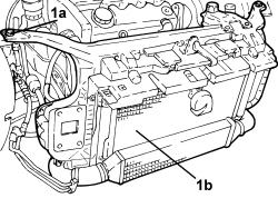
1. Loosen the colllar and disconnect the oil vapour pipes from the cam cover.
2. Disconnect the electrical connection for flow meter.
| Description | Connector | |
|---|---|---|
| 2 | Air flow meter | See K041 AIR FLOW METER |
3. Loosen the band, disconnect the turbocharger air outlet hose and remove.
4. Disconnec the hose from the rigid vacuum pipe.
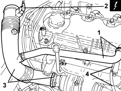
1. Unscrew the bolt, undo the clip and move the coolant pipes away from the air conditioner compressor.
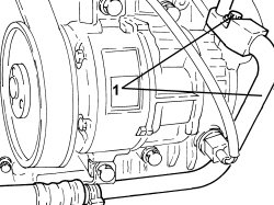
- Disconnect the fan relay.
| Description | Connector | |
|---|---|---|
| Engine fan switch relay | See J029 ENGINE FANS REMOTE CONTROL RELAY |
1. Disconnect the electrical connection from the turbocharger vane position actuator solenoid valve.
| Description | Connector | |
|---|---|---|
| 1 | Turbine variable geometry control solenoid | See L036 TURBINE VARIABLE GEOMETRY CONTROL SOLENOID VALVE |
2. Unscrew the nuts and remove the turbocharger vane position actuator control solenoid bracket.
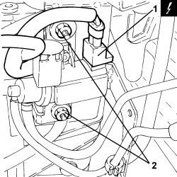
1. Disconnect the electrical connection for the Lambda sensor.
| Description | Connector | |
|---|---|---|
| 1 | Lambda sensor on pre-catalyzer | See K015 LAMBDA SENSOR ON PRE-CATALYZER |
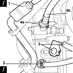
2. Disconnect the electrical connection for the reversing light switch.
| Description | Connector | |
|---|---|---|
| 2 | Reversing lights switch | See I020 REVERSING LIGHTS SWITCH |
3. Undo the bolt and release the earth lead from the gearbox.
4. Withdraw clip (4a) and remove the clutch hose (4b) from the three-way fitting.
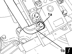
1. Undo the nut (1a) and disconnect the starter motor supply lead (1b) from the contact board.
| Description | Connector | |
|---|---|---|
| 1 | Maxifuse casing on battery | See B099 MAXI FUSE BOX ON BATTERY |
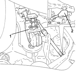
1. Disconnect the gear selector cable.
2. Disconnect the gear engagement cable.
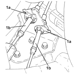
1. Open the clips (1a) and release the gear selector and engagement cables (1b) from the mounting bracket.
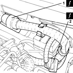
1. Connect the electrical connection for the injection control unit.
| Description | Connector | |
|---|---|---|
| 1 | Engine management control unit | See M010 ENGINE MANAGEMENT ECU |
2. Disconnect the engine prewired junction.
| Description | Connector | |
|---|---|---|
| 2 | Engine cables/engine services cable coupling | See D029 ENGINE CABLES/ENGINE SERVICES CABLE COUPLING |
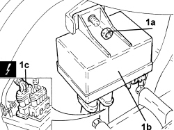
1. Undo nut (1a), remove the glow plug preheating control unit (1b) and disconnect electrical connection (1c).
| Description | Connector | |
|---|---|---|
| 1c | Heater plugs control unit | See M015 PLUG PREHEATING CONTROL UNIT |
1. Disconnect the water supply and return pipes to the heater.
2. Disconnect the single-acting valve from the brake servo.
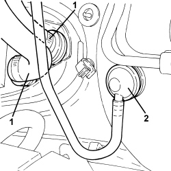
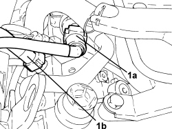
1. Disconnect pipe (1a) from the fuel return manifold and pipe (1b) from the pressure pump.
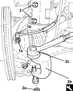
1. Undo the bolt (1a) and move the ABS sensor (1b) from the pillar.
2. Unscrew the nut (2a), fit the tool (2b) and disconnect the left steering link (2c) from the knuckle.
| Tool | Description | Function | Validity |
|---|---|---|---|
| 1871000700 | Extractor | Extracting steering rod from steering knuckle |
3. Undo the bolts securing the left front shock absorber to the knuckle.
- Move back the left half-axle from the differential.
- Proceed in the same way for the right side.
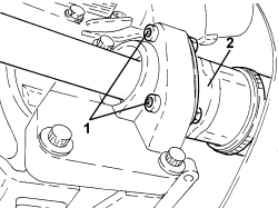
1. Undo the bolts securing the intermediate driveshaft to the mount.
2. Withdraw the right half-axle complete with intermediate driveshaft from the differential and secure to the steering box.
1. Support the power unit using a hydraulic hoist (1a) and the tool (1b) connected to the mounting brackets (1c).
| Tool | Description | Function | Validity |
|---|---|---|---|
| 1871001700 | Balance | Removing/ refitting power unit |
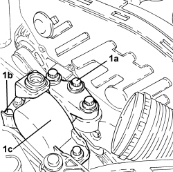
1. Undo the bolts (1a), (1b), then remove the power unit timing side front support flexible mounting (1c).
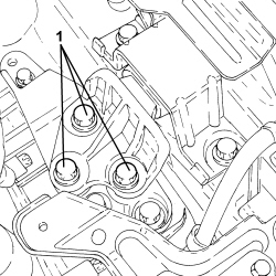
1. Undo the bolts fixing the gearbox side support flexible mounting to the rigid support.
- Remove the power unit from the engine compartment and secure to a platform.
- Release the power unit from the support tools.
Refitting
- Fit the support tools to the power unit.
- Place the power unit in its housing using the hydraulic hoist.
- Tighten the bolts fixing the gearbox side power unit flexible mounting block to the rigid support to the recommended torque.
| Component | Fastening | dia | Value (daNm) | Validity |
|---|---|---|---|---|
| Gearbox side support flexible mounting to rigid support | Bolt | M12 | 7.6 ÷ 8.4 + 45° | 1.9 Multijet |
- Place the power unit timing side front mount flexible mounting block in its housing and secure it by tightening the bolts to the recommended torque.
| Component | Fastening | dia | Value (daNm) | Validity |
|---|---|---|---|---|
| Timing side power unit to rigid support flexible mounting | Bolt | M12 | 9.0 ÷ 11.0 | 1.3 Multijet 1.9 Multijet |
| Component | Fastening | dia | Value (daNm) | Validity |
|---|---|---|---|---|
| Timing side power unit flexible mounting to bodyshell | Bolt | M10 | 5.4 ÷ 6.6 |
- Remove the hydraulic hoist and tool used for supporting the power unit safely.
- Place the left half-axle back in its housing.
- Tighten the bolts fixing the left front shock absorber to the steering knuckle to the recommended torque.
To tighten to torque, position the torque wrench on the nut and not on the bolt.
| Component | Fastening | dia | Value (daNm) | Validity |
|---|---|---|---|---|
| Front shock absorber - steering knuckle side | Bolt (to be replaced) | M12 | 10.3 ÷ 12.6 + 45° |
- Connect the left steering links to the knuckle and tighten the nut to the specified torque.
| Component | Fastening | dia | Value (daNm) | Validity |
|---|---|---|---|---|
| Steering rod to steering knuckle | Nut | M10 | 3.6 ÷ 4.4 |
- Connect the ABS sensor to the knuckle and secure it using the bolt.
- Proceed in the same way for the right side.
- Tighten the bolts fixing the intermdiate driveshaft to the mounting to the recommended torque.
| Component | Fastening | dia | Value (daNm) | Validity |
|---|---|---|---|---|
| Intermediate driveshaft - support side | Bolt | M6 | 0.6 ÷ 1.0 | 1.9 Multijet |
- Connect the pipe to the fuel return manifold and the pipe to the pressure pump.
- Connect the single-acting valve to the brake servo.
- Connect the water supply and return pipes to the heater.
- Place the heater plug control unit in position, secure it using the nut and connect the electrical connection.
- Connect the engine prewired junction.
- Connect the electrical connection for the injection control unit.
- Fasten the gear selection and engagement cables to the mounting bracket securing them using the clips.
- Connect the gear engagement cable.
- Connect the gear selector cable.
- Connect the starter motor earth lead to the contact board and secure it using the nut.
- Connect the clutch fluid hose to the three-way fitting and do up the clip.
- Connect the earth lead to the gearbox and secure it using the nut.
- Connect the electrical connection for the reversing light switch.
- Connect the electrical connection for the Lambda sensor.
- Refit the turbocharger vane position actuator control solenoid valve bracket in its seat and secure with nuts.
- Connect the electrical connection from the turbocharger vane position actuator solenoid valve.
- Connect the fan relay.
- Refit the coolant pipes to the air conditioner compressor in their seats, do up the clip and tighten the bolt.
- Connect the hose to the rigid vacuum pipe.
- Place the air outllet hose from the turbocharger back in its housing and secure it using the band.
- Connect the electrical connection for flow meter.
- Connect the oil vapour pipe to the cam cover and secure with the band.
- Refit the wing union assembly ring in its seat and secure with the bolts.
- Connect the degassing pipe to the expansion tank nd secure it using the band.
- Connect the coolant pipe to the thermostat and secure it using the band.
- Connect the hose to the coolant return pipe to the water pump and secure it using the band.
- Connect the bonnet opening cable to the lock.
- Connect the earth lead to the bodyshell.
- Connect the rear dashboard junctions.
- Connect the electrical connection for the multi-stage valve.
- Connect the air outlet hose from the intercooler and secure with the band.
- Connect the air outlet pipe to the turbocharger and secure it using the band.
- Connect the vacuum pipe to the turbocharger actuator.
Op. 5540B08 RIGHT FRONT HEADLAMP - R.R
Op. 5540B07 LEFT FRONT HEADLAMP - R.R
Op. 7210A18 R.R FRONT CROSSMEMBER
Op. 4450B12 FRONT WHEELS (TWO) - R+R
Op. 1008C32 GEARBOX LOWER REACTION ROD -R.R.
Op. 1076B72 INTERMEDIATE EXHAUST PIPE WITH HOSE SECTION - R+R
Op. 4410D17 REINFORCEMENT FOR FRONT SUSPENSION CROSSMEMBER - R.R.
Op. 0010T40 CHANGE MANUAL GEARBOX OIL
Op. 0010T84 COOLANT FOR AIR CONDITIONING SYSTEM - DEHYDRATE AND REPRESSURIZE
Op. 7055B54 UNDER ENGINE PROTECTION/GUARD - R.R.
Op. 1048A10 AIR FILTER ASSEMBLY - R.R.
Op. 1016A10 SOUND-PROOFING COVER - R.R
Op. 0010T64 BRAKE AND/OR CLUTCH FLUID CHECK LEVEL AND TOP UP AS NECESSARY
Op. 0010T67 HYDRAULIC CLUTCH SYSTEM - BLEED AIR
Op. 5530B52 BATTERY SUPPORT/DRIP TRAY - R.R
Op. 0010T20 ENGINE COOLANT - CHANGE
- Remove the vehicle from the lift.
Removing
- Position the vehicle on a lift.
Op. 5530B52 BATTERY SUPPORT/DRIP TRAY - R.R
Op. 1048A10 AIR FILTER ASSEMBLY - R.R.
Op. 0010T20 ENGINE COOLANT - CHANGE
Op. 0010T40 CHANGE MANUAL GEARBOX OIL
Op. 4410D17 REINFORCEMENT FOR FRONT SUSPENSION CROSSMEMBER - R.R.
Op. 1008C32 GEARBOX LOWER REACTION ROD -R.R.
Op. 4450B12 FRONT WHEELS (TWO) - R+R
Op. 1072C44 EXHAUST MANIFOLD HEAT SHIELD - R+R
- Disconnect the exhaust pipe from the flange and from the flexible mountings, move it aside and secure it appropriately.
1. Loosen the band and disconnect the air outlet pipe from the radiator.
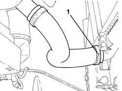
1. Loosen the band and disconnect the radiator water inlet pipe.
2. Loosen the band and disconnect the engine cooling system supply pipe.
3. Loosen the band and disconnect the degassing pipe.
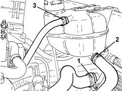
1. Loosen the bands and disconnect the heater water supply and return pipes.
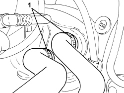
1. Disconnect the electrical connection for the reversing light switch.
| Description | Connector | |
|---|---|---|
| 1 | Reversing lights switch | See I020 REVERSING LIGHTS SWITCH |
2. Undo the bolts and move the clutch control actuator aside.
3. Undo the nut and disconnect the earth lead.
| Description | Connector | |
|---|---|---|
| 3 | Battery earth on engine | See C002 BATTERY EARTH ON ENGINE |
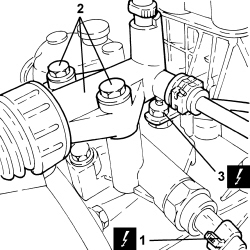
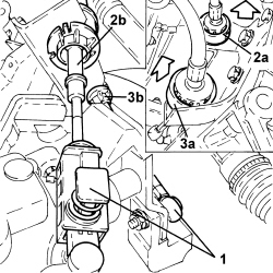
1. Disconnect the gear selector and engagement cables.
2. Move the locking bush (2a) backwards and remove the gear selector cable (2b).
3. Move the locking bush (3a) backwards and remove the gear engagement cable (3b).
1. Connect the electrical connection for the injection control unit.
| Description | Connector | |
|---|---|---|
| 1 | Engine management control unit | See M010 ENGINE MANAGEMENT ECU |
2. Disconnect the engine coupling.
| Description | Connector | |
|---|---|---|
| 2 | Engine cables/engine services cable coupling | See D029 ENGINE CABLES/ENGINE SERVICES CABLE COUPLING |
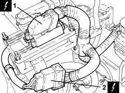
1. Disconnect the single-acting valve from the brake servo.
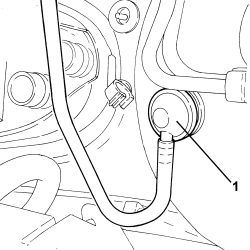
1. Disconnect the fuel pipe rapid connector.
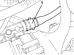
1. Disconnect the intermediate rapid connector for the fuel vapour pipe.
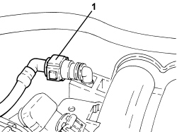
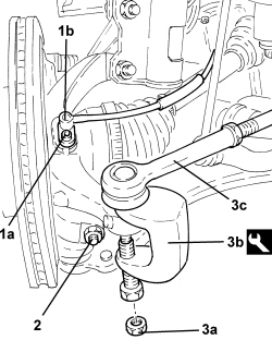
1. Undo the bolt (1a) and move the ABS sensor (1b) from the pillar.
2. Undo the bolt securing the front suspension left track control arm to the steering knuckle
3. Unscrew the nut (3a), fit the tool (3b) and disconnect the left steering link (3c) from the knuckle.
| Tool | Description | Function | Validity |
|---|---|---|---|
| 1871000700 | Extractor | Extracting steering rod from steering knuckle |
- Proceed in the same way for the right side.
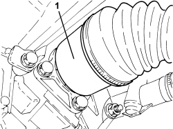
1. Disconnect the left driveshaft from the differential and secure it appropriately.
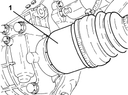
1. Disconnect the right driveshaft from the differential and secure it appropriately.
- Lower the lift and place a suitable support underneath the power unit.
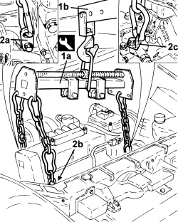
1. Fit the element (1a) on the hydraulic hoist (1b).
| Tool | Description | Function | Validity |
|---|---|---|---|
| 1871001700 | Balance | Removing/ refitting power unit |
2. Attach the power unit at the points shown in the diagram (2a), (2b) and (2c).
- Gently raise the power unit and make sure that the chains have the same tension.
1. Undo the bolts fixing the flexible mounting to the timing side rigid support.
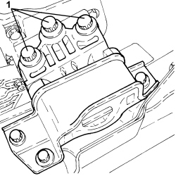
1. Undo the bolts fixing the flexible mounting to the gearbox side rigid power unit support.
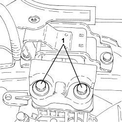
- Lower the power unit until it rests on the board positioned previously.
- Release the power unit from the support tools.
Refitting
- Fit the support tools to the power unit.
- Place the power unit in its housing using the hydraulic hoist.
- Tighten the bolts fixing the flexible mounting to the gearbox side rigid power unit support to the recommended torque.
| Component | Fastening | dia | Value (daNm) | Validity |
|---|---|---|---|---|
| Gearbox side support flexible mounting to rigid support | Bolt | M12 | 9.5 ÷ 10.5 | 1.2 8v 1.4 8v 1.4 16v 1.3 Multijet |
- Tighten the bolts fixing the flexible mounting to the timing side rigid power unit support.
| Component | Fastening | dia | Value (daNm) | Validity |
|---|---|---|---|---|
| Timing side power unit rigid support flexible mounting | Bolt | M10 | 5.4 ÷ 6.6 | 1.2 8v 1.4 8v 1.4 16v |
- Remove the hydraulic hoist and tool used for supporting the power unit safely.
- Place the right driveshaft back in its housing.
- Place the left driveshaft back in its housing.
- Connect the left steering links to the knuckle and tighten the nut to the specified torque.
| Component | Fastening | dia | Value (daNm) | Validity |
|---|---|---|---|---|
| Steering rod to steering knuckle | Nut | M10 | 3.6 ÷ 4.4 |
- Tighten the bolt securing the front suspension left track control arm to the steering knuckle
| Component | Fastening | dia | Value (daNm) | Validity |
|---|---|---|---|---|
| Front suspension lower track control arm - steering knuckle side | Bolt | M10 | 5.4 ÷ 6.6 |
- Connect the ABS sensor to the knuckle and secure it using the bolt.
- Proceed in the same way for the right side.
- Connect the intermediate rapid connector for the fuel vapour pipe.
- Connect the fuel pipe rapid connector to the rail.
- Connect the single-acting valve to the brake servo.
- Connect the engine coupling.
- Connect the electrical connection for the injection control unit.
- Place the gear selector and engagement cables complete with centering bushes back in their housings.
- Connect the gear selector and engagement cables.
- Connect the battery earth lead.
- Place the hydraulic clutch actuator in position and secure it tightening the bolts to the recommended torque.
| Component | Fastening | dia | Value (daNm) | Validity |
|---|---|---|---|---|
| Clutch hydraulic actuator | Bolt | M8 | 1.8 ÷ 2.2 | 1.2 8v 1.4 8v 1.4 16v 1.3 Multijet 75bhp |
- Connect the electrical connection for the reversing light switch.
- Connect the heater water supply and return pipes and secure them using the bands.
- Connect the degassing pipe and secure it using the band.
- Connect the engine cooling system supply pipe and secure it using the band.
- Connect the raidator coolant inlet pipe and secure it using the band.
- Connect the raidator coolant outlet pipe and secure it using the band.
- Connect the exhaust pipe to the flange and to the flexible mountings.
Op. 1072C44 EXHAUST MANIFOLD HEAT SHIELD - R+R
Op. 4450B12 FRONT WHEELS (TWO) - R+R
Op. 1008C32 GEARBOX LOWER REACTION ROD -R.R.
Op. 4410D17 REINFORCEMENT FOR FRONT SUSPENSION CROSSMEMBER - R.R.
Op. 0010T40 CHANGE MANUAL GEARBOX OIL
Op. 0010T20 ENGINE COOLANT - CHANGE
Op. 1048A10 AIR FILTER ASSEMBLY - R.R.
Op. 0010T64 BRAKE AND/OR CLUTCH FLUID CHECK LEVEL AND TOP UP AS NECESSARY
Op. 0010T67 HYDRAULIC CLUTCH SYSTEM - BLEED AIR
Op. 5530B52 BATTERY SUPPORT/DRIP TRAY - R.R
- Remove the vehicle from the lift.
Removing
Op. 5530B52 BATTERY SUPPORT/DRIP TRAY - R.R
Op. 1048A23 COLD AIR INTAKE FOR AIR FILTER - R.R
Op. 1048A10 AIR FILTER ASSEMBLY - R.R.
Op. 0010T84 COOLANT FOR AIR CONDITIONING SYSTEM - DEHYDRATE AND REPRESSURIZE
Op. 7055B66 ENGINE COMPARTMENT DUST COVER IN RIGHT FRONT WHEEL ARCH - R.R.
Op. 0010T20 ENGINE COOLANT - CHANGE
Op. 0010T40 CHANGE MANUAL GEARBOX OIL
Op. 4410D17 REINFORCEMENT FOR FRONT SUSPENSION CROSSMEMBER - R.R.
Op. 1008C32 GEARBOX LOWER REACTION ROD -R.R.
Op. 4450B12 FRONT WHEELS (TWO) - R+R
1. Undo the brake/clutch fluid reservoir cap and tighten the tool.
| Tool | Description | Function | Validity |
|---|---|---|---|
| 2000001400 | Plug | Brake/ clutch system vacuum |
1. Loosen the band (1a) and disconnect the heat exchanger flexible air supply pipe (1b).
2. Loosen the band (2a) and disconnect the throttle casing flexible air supply pipe (2b).
3. Undo the bolt fixing the heat exchanger rigid air supply pipe to the front end.
1. Undo the bolt (1a) fixing the heat exchanger rigid air inlet pipe (1b) to the front end.
2. Undo the bolt (2a) fixing the throttle casing rigid air supply pipe (2b) to the front end.
3. Undo the bolts (3a) and remove the air-air heat exchanger assembly (3b).
1. Undo the bolt (1a) fixing the flange for the air conditioning compressor inlet and supply pipes (1b).
2. Undo the bolt (2a) fixing the air conditioning compressor and inlet and supply pipes bracket (2b).
- Move the pipes disconnected previously aside and secure them appropriately.
1. Disconnect the rapid connector for the radiator lower coolant outlet pipe.
1. Disconnect the electrical connection for the reversing light switch.
| Description | Connector | |
|---|---|---|
| 1 | Reversing lights switch | See I020 REVERSING LIGHTS SWITCH |
2. Undo the bolt and remove the battery earth lead from the gearbox.
| Description | Connector | |
|---|---|---|
| 2 | Battery earth | See C001 BATTERY EARTH |
3. Withdraw the clip and disconnect the flexible pipe from the coaxial clutch cable actuator from the three-way fitting.
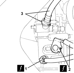
1. Disconnect the electrical connection for the heater plugs control unit.
| Description | Connector | |
|---|---|---|
| 1 | Heater plugs control unit | See M015 PLUG PREHEATING CONTROL UNIT |
1. Loosen the bands and disconnect the pipes from the engine coolant reservoir.
2. Undo the bolts (2a) and remove the engine coolant reservoir (2b).
1. Disconnect the rapid connector for the radiator upper coolant inlet pipe.
1. Disconnect the rapid connectors for the heater supply and return pipes.
2. Disconnect the single-acting valve from the brake servo.
1. Disconnect the gear selector and engagement cables.
2. Retract the cursor and disconnect the gear selector and engagement cables from the bracket.
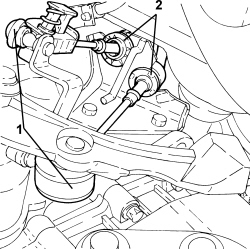
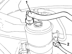
1. Disconnect the fuel supply pipe rapid connector from the fuel filter.
2. Disconnect the intermediate rapid connector for the return pipe to the fuel tank.
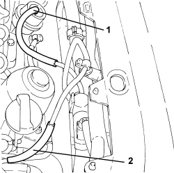
1. Disconnect the vacuum pipe from the turbocharger vane control actuator.
2. Disconnec the hose from the rigid vacuum pipe.
1. Connect the electrical connection for the injection control unit.
| Description | Connector | |
|---|---|---|
| 1 | Engine management control unit | See M010 ENGINE MANAGEMENT ECU |
2. Disconnect the engine coupling.
| Description | Connector | |
|---|---|---|
| 2 | Engine cables/engine services cable coupling | See D029 ENGINE CABLES/ENGINE SERVICES CABLE COUPLING |
3. Disconnect the electrical connection for the Lambda sensor.
| Description | Connector | |
|---|---|---|
| 3 | Lambda sensor on catalyzer | See K017 LAMBDA SENSOR ON CATALYZER |
1. Disconnect the electrical connection from the turbocharger vane control actuator solenoid valve.
| Description | Connector | |
|---|---|---|
| 1 | Turbine variable geometry control solenoid | See L036 TURBINE VARIABLE GEOMETRY CONTROL SOLENOID VALVE |
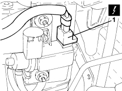
1. Disconnect the electrical connection for the fan.
| Description | Connector | |
|---|---|---|
| 1 | Engine fan motor | See N011 FAN MOTOR |
2. Disconnect the resistor electrical connection.
| Description | Connector | |
|---|---|---|
| 2 | Engine fan adjustment resistance | See O010 ENGINE FAN ADJUSTMENT RESISTANCE - 1 |
3. Undo the bolts (3a) and remove the fan (3b) from the side clips.
1. Unscrew the nut, fit the tool and disconnect the left steering link from the knuckle.
| Tool | Description | Function | Validity |
|---|---|---|---|
| 1871000700 | Extractor | Extracting steering rod from steering knuckle |
2. Undo the bolts securing the left front shock absorber to the knuckle.
3. Undo the bolt and remove the ABS sensor.
- Move back the left half-axle from the differential.
- Proceed in the same way for the right side.
1. Undo the bolts (1a) securing the intermediate driveshaft support (1b).
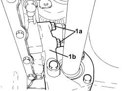
- Withdraw the right half-axle complete with intermediate driveshaft from the differential and secure to the steering box.
1. Support the power unit using a hydraulic hoist (1a) and the tool (1b) connected to the mounting brackets (1c) on the engine.
| Tool | Description | Function | Validity |
|---|---|---|---|
| 1871001700 | Balance | Removing/ refitting power unit |
- Postion a suitable footboard beneath the power unit.
1. Undo the bolts fixing the flexible mounting to the timing side rigid power unit support.
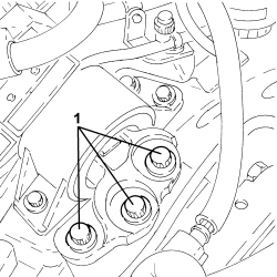
1. Undo the bolts fixing the flexible mounting to the gearbox side rigid power unit support.
- Slowly lower the power unit with the hydraulic hoist until it rests on the board positioned previously.
Refitting
- Fit the support tools to the power unit.
- Place the power unit in its housing using the hydraulic hoist.
- Tighten the bolts fixing the flexible mounting to the gearbox side rigid power unit support to the recommended torque.
| Component | Fastening | dia | Value (daNm) | Validity |
|---|---|---|---|---|
| Gearbox side support flexible mounting to rigid support | Bolt | M12 | 9.5 ÷ 10.5 | 1.2 8v 1.4 8v 1.4 16v 1.3 Multijet |
- Tighten the bolts fixing the flexible mounting to the timing side rigid power unit support.
| Component | Fastening | dia | Value (daNm) | Validity |
|---|---|---|---|---|
| Timing side power unit to rigid support flexible mounting | Bolt | M12 | 9.0 ÷ 11.0 | 1.3 Multijet 1.9 Multijet |
- Remove the hydraulic hoist and tool used for supporting the power unit.
- Place the left half-axle back in its housing.
- Tighten the new bolts fixing the left front shock absorber to the steering knuckle to the recommended torque.
To tighten to torque, position the torque wrench on the nut and not on the bolt.
| Component | Fastening | dia | Value (daNm) | Validity |
|---|---|---|---|---|
| Front shock absorber - steering knuckle side | Bolt (to be replaced) | M12 | 10.3 ÷ 12.6 + 45° |
- Connect the left steering links to the knuckle and tighten the nut to the specified torque.
| Component | Fastening | dia | Value (daNm) | Validity |
|---|---|---|---|---|
| Steering rod to steering knuckle | Nut | M10 | 3.6 ÷ 4.4 |
- Connect the ABS sensor to the knuckle and secure it using the bolt.
- Proceed in the same way for the right side.
- Tighten the bolts fixing the intermdiate driveshaft to the mounting to the recommended torque.
| Component | Fastening | dia | Value (daNm) | Validity |
|---|---|---|---|---|
| Intermediate driveshaft bearing support | Bolt | M8 | 2.0 ÷ 2.4 | 1.3 Multijet |
- Place the fan in its housing and secure it using the bolts.
- Connect the resistor electrical connection.
- Connect the electrical connection for the fan.
- Connect the electrical connection of the turbocharger vane control actuator solenoid valve.
- Connect the electrical connection for the Lambda sensor.
- Connect the engine coupling.
- Connect the electrical connection for the injection control unit.
- Connect the hose to the rigid vacuum pipe.
- Connect the vacuum pipe to the turbocharger vane control actuator.
- Connect the intermediate rapid connector for the return pipe to the fuel tank.
- Connect the fuel supply pipe rapid connector to the fuel filter.
- Introduce the two quick-fits for hoses in the openings in the bracket keeping the cursors retracted and inserting them fully into the seats using manual pressure; release the cursors.
- Connect the ends of the gear selection-engagement cables to the ends of the gear lever.
- Connect the single-acting valve to the brake servo.
- Connect the rapid connectors for the heater supply and return pipes.
- Connect the rapid connector for the radiator upper coolant inlet pipe.
- Fit the engine cooling reservoir in place and secure it using the bolts.
- Connect the pipes to the engine coolant reservoir.
- Connect the electrical connection for the heater plugs control unit.
- Connect the hose to the coaxial clutch control actuator three-way fitting.
- Refit the battery earth lead to its seat on the gearbox.
- Connect the electrical connection for the reversing light switch.
- Connect the rapid connector for the lower coolant outlet pipe to the radiator.
- Tighten the bolt fixing the air conditioning compressor and the inlet and supply pipe bracket to the recommended torque.
| Component | Fastening | dia | Value (daNm) | Validity |
|---|---|---|---|---|
| Compressor | Bolt | M8x1.25x80 | 2.0 ÷ 2.4 | 1.3 Multijet |
- Tighten the bolt for the connector for the air conditioning compressor inlet and supply pipes to the recommended torque.
| Component | Fastening | dia | Value (daNm) | Validity |
|---|---|---|---|---|
| Pipe connector on compressor | Bolt | M8 | 1.8 ÷ 2.2 | 1.3 Multijet 1.9 Multijet |
- Place the air/air heat exchanger assembly in its housing and secure it using the bolts.
- Tighten the bolt fixing the throttle casing rigid air supply pipe to the front end.
- Tighten the bolt fixing the heat exchanger rigid air inlet pipe to the front end.
- Tighten the bolt fixing the heat exchanger rigid air supply pipe to the front end.
- Connect the flexible air supply pipe to the throttle casing.
- Connect the flexible air supply pipe to the heat exchanger.
Op. 4450B12 FRONT WHEELS (TWO) - R+R
Op. 1008C32 GEARBOX LOWER REACTION ROD -R.R.
Op. 4410D17 REINFORCEMENT FOR FRONT SUSPENSION CROSSMEMBER - R.R.
Op. 7055B66 ENGINE COMPARTMENT DUST COVER IN RIGHT FRONT WHEEL ARCH - R.R.
Op. 1048A10 AIR FILTER ASSEMBLY - R.R.
Op. 1048A23 COLD AIR INTAKE FOR AIR FILTER - R.R
Op. 5530B52 BATTERY SUPPORT/DRIP TRAY - R.R
Op. 0010T40 CHANGE MANUAL GEARBOX OIL
Op. 0010T20 ENGINE COOLANT - CHANGE
Op. 0010T84 COOLANT FOR AIR CONDITIONING SYSTEM - DEHYDRATE AND REPRESSURIZE
Removing
Op. 5530B52 BATTERY SUPPORT/DRIP TRAY - R.R
Op. 1048A23 COLD AIR INTAKE FOR AIR FILTER - R.R
Op. 1048A10 AIR FILTER ASSEMBLY - R.R.
Op. 0010T84 COOLANT FOR AIR CONDITIONING SYSTEM - DEHYDRATE AND REPRESSURIZE
Op. 7055B66 ENGINE COMPARTMENT DUST COVER IN RIGHT FRONT WHEEL ARCH - R.R.
Op. 0010T20 ENGINE COOLANT - CHANGE
Op. 0010T40 CHANGE MANUAL GEARBOX OIL
Op. 4410D17 REINFORCEMENT FOR FRONT SUSPENSION CROSSMEMBER - R.R.
Op. 1008C32 GEARBOX LOWER REACTION ROD -R.R.
Op. 4450B12 FRONT WHEELS (TWO) - R+R
1. Undo the brake/clutch fluid reservoir cap and tighten the tool.
| Tool | Description | Function | Validity |
|---|---|---|---|
| 2000001400 | Plug | Brake/ clutch system vacuum |
1. Loosen the band (1a) and disconnect the heat exchanger flexible air supply pipe (1b).
2. Loosen the band (2a) and disconnect the throttle casing flexible air supply pipe (2b).
3. Undo the bolt fixing the heat exchanger rigid air supply pipe to the front end.
1. Undo the bolt (1a) fixing the heat exchanger rigid air inlet pipe (1b) to the front end.
2. Undo the bolt (2a) fixing the throttle casing rigid air supply pipe (2b) to the front end.
3. Undo the bolts (3a) and remove the air-air heat exchanger assembly (3b).
1. Undo the bolt (1a) fixing the flange for the air conditioning compressor inlet and supply pipes (1b).
2. Undo the bolt (2a) fixing the air conditioning compressor and inlet and supply pipes bracket (2b).
- Move the pipes disconnected previously aside and secure them appropriately.
1. Disconnect the rapid connector for the radiator lower coolant outlet pipe.
1. Disconnect the electrical connection for the reversing light switch.
| Description | Connector | |
|---|---|---|
| 1 | Reversing lights switch | See I020 REVERSING LIGHTS SWITCH |
2. Undo the bolt (2a) and disconnect the battery earth lead (2b) from the gearbox.
| Description | Connector | |
|---|---|---|
| 2b | Battery earth | See C001 BATTERY EARTH |
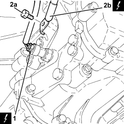
1. Disconnect the electrical connection for the heater plugs control unit.
| Description | Connector | |
|---|---|---|
| 1 | Heater plugs control unit | See M015 PLUG PREHEATING CONTROL UNIT |
1. Loosen the bands and disconnect the pipes from the engine coolant reservoir.
2. Undo the bolts (2a) and remove the engine coolant reservoir (2b).
1. Disconnect the rapid connector for the radiator upper coolant inlet pipe.
1. Disconnect the rapid connectors for the heater supply and return pipes.
2. Disconnect the single-acting valve from the brake servo.
1. Disconnect the gear selector and engagement cables.
2. Retract the cursor and disconnect the gear selector and engagement cables from the bracket.
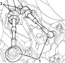
1. Disconnect the fuel supply pipe rapid connector from the fuel filter.
2. Disconnect the intermediate rapid connector for the return pipe to the fuel tank.
1. Disconnect the vacuum pipe from the turbocharger vane control actuator.
2. Disconnec the hose from the rigid vacuum pipe.
1. Connect the electrical connection for the injection control unit.
| Description | Connector | |
|---|---|---|
| 1 | Engine management control unit | See M010 ENGINE MANAGEMENT ECU |
2. Disconnect the engine coupling.
| Description | Connector | |
|---|---|---|
| 2 | Engine cables/engine services cable coupling | See D029 ENGINE CABLES/ENGINE SERVICES CABLE COUPLING |
3. Disconnect the electrical connection for the Lambda sensor.
| Description | Connector | |
|---|---|---|
| 3 | Lambda sensor on catalyzer | See K017 LAMBDA SENSOR ON CATALYZER |
1. Disconnect the electrical connection from the turbocharger vane control actuator solenoid valve.
| Description | Connector | |
|---|---|---|
| 1 | Turbine variable geometry control solenoid | See L036 TURBINE VARIABLE GEOMETRY CONTROL SOLENOID VALVE |
1. Disconnect the electrical connection for the fan.
| Description | Connector | |
|---|---|---|
| 1 | Engine fan motor | See N011 FAN MOTOR |
2. Disconnect the resistor electrical connection.
| Description | Connector | |
|---|---|---|
| 2 | Engine fan adjustment resistance | See O010 ENGINE FAN ADJUSTMENT RESISTANCE - 1 |
3. Undo the bolts (3a) and remove the fan (3b) from the side clips.
1. Unscrew the nut, fit the tool and disconnect the left steering link from the knuckle.
| Tool | Description | Function | Validity |
|---|---|---|---|
| 1871000700 | Extractor | Extracting steering rod from steering knuckle |
2. Undo the bolts securing the left front shock absorber to the knuckle.
3. Undo the bolt and remove the ABS sensor.
- Move back the left half-axle from the differential.
- Proceed in the same way for the right side.
1. Undo the bolts (1a) securing the intermediate driveshaft support (1b).
- Withdraw the right half-axle complete with intermediate driveshaft from the differential and secure to the steering box.
1. Support the power unit using a hydraulic hoist (1a) and the tool (1b) connected to the mounting brackets (1c) on the engine.
| Tool | Description | Function | Validity |
|---|---|---|---|
| 1871001700 | Balance | Removing/ refitting power unit |
- Postion a suitable footboard beneath the power unit.
1. Undo the bolts fixing the flexible mounting to the timing side rigid power unit support.
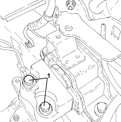
1. Undo the bolts fixing the flexible mounting to the gearbox side rigid power unit support.
- Slowly lower the power unit with the hydraulic hoist until it rests on the board positioned previously.
Refitting
- Fit the support tools to the power unit.
- Place the power unit in its housing using the hydraulic hoist.
- Tighten the bolts fixing the flexible mounting to the gearbox side rigid power unit support to the recommended torque.
| Component | Fastening | dia | Value (daNm) | Validity |
|---|---|---|---|---|
| Gearbox side support flexible mounting to rigid support | Bolt | M12 | 9.5 ÷ 10.5 | 1.2 8v 1.4 8v 1.4 16v 1.3 Multijet |
- Tighten the bolts fixing the flexible mounting to the timing side rigid power unit support.
| Component | Fastening | dia | Value (daNm) | Validity |
|---|---|---|---|---|
| Timing side power unit to rigid support flexible mounting | Bolt | M12 | 9.0 ÷ 11.0 | 1.3 Multijet 1.9 Multijet |
- Remove the hydraulic hoist and tool used for supporting the power unit.
- Place the left half-axle back in its housing.
- Tighten the new bolts fixing the left front shock absorber to the steering knuckle to the recommended torque.
To tighten to torque, position the torque wrench on the nut and not on the bolt.
| Component | Fastening | dia | Value (daNm) | Validity |
|---|---|---|---|---|
| Front shock absorber - steering knuckle side | Bolt (to be replaced) | M12 | 10.3 ÷ 12.6 + 45° |
- Connect the left steering links to the knuckle and tighten the nut to the specified torque.
| Component | Fastening | dia | Value (daNm) | Validity |
|---|---|---|---|---|
| Steering rod to steering knuckle | Nut | M10 | 3.6 ÷ 4.4 |
- Connect the ABS sensor to the knuckle and secure it using the bolt.
- Proceed in the same way for the right side.
- Tighten the bolts fixing the intermdiate driveshaft to the mounting to the recommended torque.
| Component | Fastening | dia | Value (daNm) | Validity |
|---|---|---|---|---|
| Intermediate driveshaft bearing support | Bolt | M8 | 2.0 ÷ 2.4 | 1.3 Multijet |
- Place the fan in its housing and secure it using the bolts.
- Connect the resistor electrical connection.
- Connect the electrical connection for the fan.
- Connect the electrical connection of the turbocharger vane control actuator solenoid valve.
- Connect the electrical connection for the Lambda sensor.
- Connect the engine coupling.
- Connect the electrical connection for the injection control unit.
- Connect the hose to the rigid vacuum pipe.
- Connect the vacuum pipe to the turbocharger vane control actuator.
- Connect the intermediate rapid connector for the return pipe to the fuel tank.
- Connect the fuel supply pipe rapid connector to the fuel filter.
- Introduce the two quick-fits for hoses in the openings in the bracket keeping the cursors retracted and inserting them fully into the seats using manual pressure; release the cursors.
- Connect the ends of the gear selection-engagement cables to the ends of the gear lever.
- Connect the single-acting valve to the brake servo.
- Connect the rapid connectors for the heater supply and return pipes.
- Connect the rapid connector for the radiator upper coolant inlet pipe.
- Fit the engine cooling reservoir in place and secure it using the bolts.
- Connect the pipes to the engine coolant reservoir.
- Connect the electrical connection for the heater plugs control unit.
- Connect the hose to the coaxial clutch control actuator three-way fitting.
- Refit the battery earth lead to its seat on the gearbox.
- Connect the electrical connection for the reversing light switch.
- Connect the rapid connector for the lower coolant outlet pipe to the radiator.
- Tighten the bolt fixing the air conditioning compressor and the inlet and supply pipe bracket to the recommended torque.
| Component | Fastening | dia | Value (daNm) | Validity |
|---|---|---|---|---|
| Compressor | Bolt | M8x1.25x80 | 2.0 ÷ 2.4 | 1.3 Multijet |
- Tighten the bolt for the connector for the air conditioning compressor inlet and supply pipes to the recommended torque.
| Component | Fastening | dia | Value (daNm) | Validity |
|---|---|---|---|---|
| Pipe connector on compressor | Bolt | M8 | 1.8 ÷ 2.2 | 1.3 Multijet 1.9 Multijet |
- Place the air/air heat exchanger assembly in its housing and secure it using the bolts.
- Tighten the bolt fixing the throttle casing rigid air supply pipe to the front end.
- Tighten the bolt fixing the heat exchanger rigid air inlet pipe to the front end.
- Tighten the bolt fixing the heat exchanger rigid air supply pipe to the front end.
- Connect the flexible air supply pipe to the throttle casing.
- Connect the flexible air supply pipe to the heat exchanger.
Op. 4450B12 FRONT WHEELS (TWO) - R+R
Op. 1008C32 GEARBOX LOWER REACTION ROD -R.R.
Op. 4410D17 REINFORCEMENT FOR FRONT SUSPENSION CROSSMEMBER - R.R.
Op. 7055B66 ENGINE COMPARTMENT DUST COVER IN RIGHT FRONT WHEEL ARCH - R.R.
Op. 1048A10 AIR FILTER ASSEMBLY - R.R.
Op. 1048A23 COLD AIR INTAKE FOR AIR FILTER - R.R
Op. 5530B52 BATTERY SUPPORT/DRIP TRAY - R.R
Op. 0010T40 CHANGE MANUAL GEARBOX OIL
Op. 0010T20 ENGINE COOLANT - CHANGE
Op. 0010T84 COOLANT FOR AIR CONDITIONING SYSTEM - DEHYDRATE AND REPRESSURIZE
Removing
Op. 5530B52 BATTERY SUPPORT/DRIP TRAY - R.R
Op. 1048A10 AIR FILTER ASSEMBLY - R.R.
Op. 1048A32 HOSE FROM AIR FILTER TO INTAKE MANIFOLD - R + R
Op. 1072C44 EXHAUST MANIFOLD HEAT SHIELD - R+R
Op. 1072C16 EXHAUST MANIFOLD WITH CATALYTIC CONVERTER - R.R.
Op. 0010T20 ENGINE COOLANT - CHANGE
Op. 0010T40 CHANGE MANUAL GEARBOX OIL
Op. 0010T84 COOLANT FOR AIR CONDITIONING SYSTEM - DEHYDRATE AND REPRESSURIZE
Op. 4410D17 REINFORCEMENT FOR FRONT SUSPENSION CROSSMEMBER - R.R.
Op. 1008C32 GEARBOX LOWER REACTION ROD -R.R.
Op. 4450B12 FRONT WHEELS (TWO) - R+R
1. Undo the nuts (1a) and the bolt (1b) and disconnect the exhaust pipe from the catalytic converter; keep the gasket.
- Disconnect the exhaust pipe from the flexible mountings, move it aside and secure it appropriately.
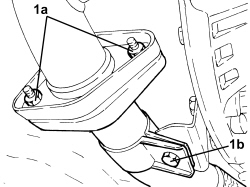
1. Loosen the band and disconnect the air outlet pipe from the radiator.
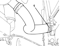
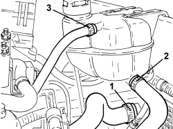
1. Loosen the band and disconnect the radiator water inlet pipe.
2. Loosen the band and disconnect the engine cooling system supply pipe.
3. Loosen the band and disconnect the degassing pipe.
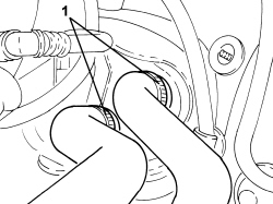
1. Loosen the bands and disconnect the heater water supply and return pipes.
1. Disconnect the electrical connection for the reversing switch.
| Description | Connector | |
|---|---|---|
| 1 | Reversing lights switch | See I020 REVERSING LIGHTS SWITCH |
2. Undo the bolts and move the clutch control actuator aside.
3. Undo the nut and disconnect the earth lead.
| Description | Connector | |
|---|---|---|
| 3 | Battery earth on engine | See C002 BATTERY EARTH ON ENGINE |
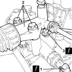
- Undo the nut and disconnect the starter motor supply lead from the contact board.
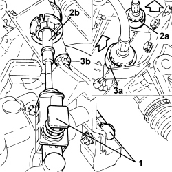
1. Disconnect the gear selector and engagement cables.
2. Move the locking cursor (2a) backwards and remove the gear selector cable (2b).
3. Move the locking cursor (3a) backwards and remove the gear engagement cable (3b).
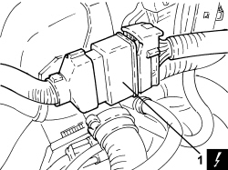
1. Disconnect the electrical connection for the injection/ignition control unit.
| Description | Connector | |
|---|---|---|
| 1 | Engine management control unit | See M010 ENGINE MANAGEMENT ECU |
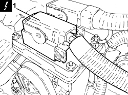
1. Disconnect the engine front coupling.
| Description | Connector | |
|---|---|---|
| 2 | Front/engine coupling | See D004 FRONT/ENGINE COUPLING |
1. Disconnect the single-acting valve from the brake servo and move it to one side.
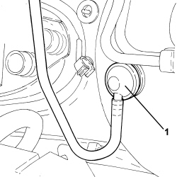
1. Disconnect the fuel pipe rapid connector from the rail.
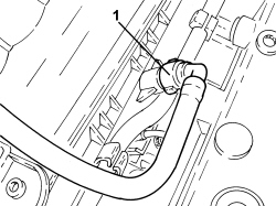
1. Disconnect the intermediate rapid connector for the fuel vapour pipe.
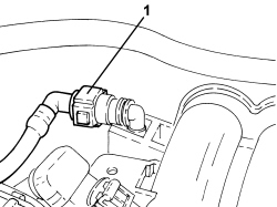
1. Undo the bolt (1a) and move the ABS sensor (1b) from the pillar.
2. Undo the bolt securing the front suspension left track control arm to the steering knuckle
3. Unscrew the nut (3a), fit the tool (3b) and disconnect the left steering link (3c) from the knuckle.
| Tool | Description | Function | Validity |
|---|---|---|---|
| 1871000700 | Extractor | Extracting steering rod from steering knuckle |
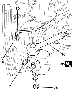
- Proceed in the same way for the right side.
1. Disconnect the left driveshaft from the differential and secure it appropriately.
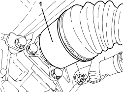
1. Disconnect the right driveshaft from the differential and secure it appropriately.
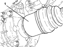
1. Disconnect the rapid connector for the air conditioning coolant supply pipe.
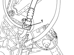
1. Disconnect the rapid connector for the air conditioning coolant return pipe.
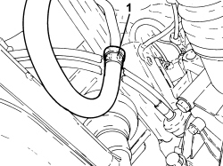
- Lower the lift and place a suitable support underneath the power unit.
1. Fit the element (1a) on the hydraulic hoist (1b).
| Tool | Description | Function | Validity |
|---|---|---|---|
| 1871001700 | Balance | Removing/ refitting power unit |
2. Attach the power unit at the points shown in the diagram (2a), (2b) and (2c).
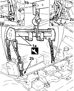
- Gently raise the power unit and make sure that the chains have the same tension.
1. Undo the bolts fixing the flexible mounting to the timing side rigid support.
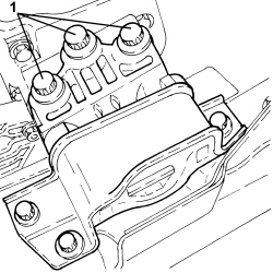
1. Undo the bolts fixing the flexible mounting to the gearbox side rigid power unit support.
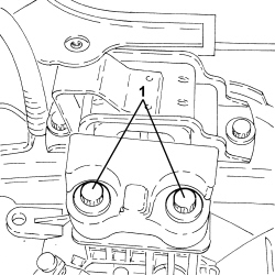
- Lower the power unit until it rests on the board positioned previously.
- Release the power unit from the support tools.
Refitting
- Fit the support tools to the power unit.
- Place the power unit in its housing using the hydraulic hoist.
- Tighten the bolts fixing the flexible mounting to the gearbox side rigid power unit support to the recommended torque.
| Component | Fastening | dia | Value (daNm) | Validity |
|---|---|---|---|---|
| Gearbox side support flexible mounting to rigid support | Bolt | M12 | 9.5 ÷ 10.5 | 1.2 8v 1.4 8v 1.4 16v 1.3 Multijet |
- Tighten the bolts fixing the flexible mounting to the timing side rigid power unit support to the recommended torque.
| Component | Fastening | dia | Value (daNm) | Validity |
|---|---|---|---|---|
| Timing side power unit rigid support flexible mounting | Bolt | M10 | 5.4 ÷ 6.6 | 1.2 8v 1.4 8v 1.4 16v |
- Remove the hydraulic hoist and tool used for supporting the power unit safely.
- Connect the rapid connector for the air conditioning coolant pipes.
- Place the right driveshaft back in its housing.
- Place the left driveshaft back in its housing.
- Connect the left steering links to the knuckle and tighten the nut to the specified torque.
| Component | Fastening | dia | Value (daNm) | Validity |
|---|---|---|---|---|
| Steering rod to steering knuckle | Nut | M10 | 3.6 ÷ 4.4 |
- Tighten the bolt securing the front suspension left track control arm to the steering knuckle to the recommended torque.
| Component | Fastening | dia | Value (daNm) | Validity |
|---|---|---|---|---|
| Front suspension lower track control arm - steering knuckle side | Bolt | M10 | 5.4 ÷ 6.6 |
- Connect the ABS sensor to the knuckle and secure it using the bolt.
- Proceed in the same way for the right side.
- Connect the intermediate rapid connector for the fuel vapour pipe.
- Connect the fuel pipe rapid connector to the rail.
- Connect the single-acting valve to the brake servo.
- Connect the engine front coupling.
- Connect the electrical connection for the injection/ignition control unit.
- Working in the engine compartment, introduce the two quick-fits for the gear selector and engagement cables in the openings in the bracket keeping the cursors retracted and inserting them fully into the seats using manual pressure until they are attached. Release the cursors.
- Using manual pressure, connect the ends of the gear selection and engagement cables to the ball joints for the levers on the gearbox.
- Connect the starter motor earth lead to the contact board and secure it using the nut.
- Connect the battery earth lead and tighten the nut.
- Place the clutch control actuator in its housing and secure it tightening the bolts to the recommended torque.
| Component | Fastening | dia | Value (daNm) | Validity |
|---|---|---|---|---|
| Clutch hydraulic actuator | Bolt | M8 | 1.8 ÷ 2.2 | 1.2 8v 1.4 8v 1.4 16v 1.3 Multijet 75bhp |
- Connect the electrical connection for the reversing switch.
- Connect the heater water supply and return pipes and secure them using the bands.
- Connect the degassing pipe to the engine coolant radiator and secure it using the band.
- Connect the system supply pipe to the engine coolant radiator and secure it using the band.
- Connect the raidator coolant inlet pipe and secure it using the band.
- Connect the radiator coolant outlet pipe and secure it using the band.
- Release the exhaust pipe from the temporary fastening and connect it to the mounting bracket using the flexible mountings.
- Place the exhaust pipe and catalytic converter gasket in its housing.
- Connect the exhaust pipe to the catalytic converter and secure by tightening the nuts to the specified torque.
| Component | Fastening | dia | Value (daNm) | Validity |
|---|---|---|---|---|
| Flange connecting catalyzer to exhaust pipe | Nut | M8 | 2.5 | 1.2 8v 1.4 8v 1.4 16v 1.3 Multijet |
- Connect the exhaust pipe collar and secure it tightening the bolt to the recommended torque.
| Component | Fastening | dia | Value (daNm) | Validity |
|---|---|---|---|---|
| Exhaust pipe to mounting bracket collar | Bolt | M8 | 2.2 ÷ 2.7 | 1.2 8v 1.4 8v 1.4 16v 1.3 Multijet |
Op. 4450B12 FRONT WHEELS (TWO) - R+R
Op. 1008C32 GEARBOX LOWER REACTION ROD -R.R.
Op. 4410D17 REINFORCEMENT FOR FRONT SUSPENSION CROSSMEMBER - R.R.
Op. 0010T84 COOLANT FOR AIR CONDITIONING SYSTEM - DEHYDRATE AND REPRESSURIZE
Op. 0010T40 CHANGE MANUAL GEARBOX OIL
Op. 0010T20 ENGINE COOLANT - CHANGE
Op. 0010T64 BRAKE AND/OR CLUTCH FLUID CHECK LEVEL AND TOP UP AS NECESSARY
Op. 0010T67 HYDRAULIC CLUTCH SYSTEM - BLEED AIR
Op. 1072C16 EXHAUST MANIFOLD WITH CATALYTIC CONVERTER - R.R.
Op. 1072C44 EXHAUST MANIFOLD HEAT SHIELD - R+R
Op. 1048A32 HOSE FROM AIR FILTER TO INTAKE MANIFOLD - R + R
Op. 1048A10 AIR FILTER ASSEMBLY - R.R.
Parts & tools for this job For 2005 Fiat Grande Punto
- PARTClutch kitSearch: Fiat Grande Punto 2005 clutch kit
- TOOLClutch alignment toolSearch: clutch alignment tool
- FLUIDGear oilSearch: Fiat Grande Punto manual gearbox oil
Links open Amazon search results in a new tab. As an Amazon Associate I earn from qualifying purchases.