
Power unit with manual gearbox - r + r
- Make
- Fiat
- Model
- Idea Factory Service Manual
- Year
- 2003–2012
- Section
- Engine and power unit › Power unit with manual gearbox - r + r
Power unit with manual gearbox - r + r
Removing
Position the vehicle on the ramp
Drain the air conditioner coolant circuit - 0010T84 coolant for air conditioning system dehydrate and recharge.
Proceed with removal - 4450B12 front or rear wheels (two) - r+r
Proceed with removal - 7055B66 Engine compartment DUST SHIELD protection in right front wheel arch - R.R.
Proceed with removal - 7055B91 Right front WHEEL ARCH LINER - R.R.
Proceed with removal - 5530B10 battery - r+r
Proceed with removal - 5530B52 Battery DRIP TRAY/SUPPORT - R.R.
Proceed with removal - 1048A10 air cleaner filtering element - replace
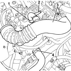
1. Loosen the collar and disconnect the engine oil vapour intake pipe from the tappet cover.
2. Disconnect the engine oil vapour inlet pipe from the intake manifold.
3. Loosen the band, disconnect the hose from the air filter to the intake manifold, intake manifold side and remove it.
4. Loosen band and disconnect the upper coolant inlet hose to the radiator, thermostat side.
Recover the coolant which comes out in a suitable container.
Removing
Position the vehicle on the ramp
Proceed with removal - 4450B12 front or rear wheels (two) - r+r
Proceed with removal
Proceed with removal - 7055B66 Engine compartment DUST SHIELD protection in right front wheel arch - R.R.
Proceed with removal - 7055B90 Left front WHEEL ARCH LINER - R.R.
Proceed with removal - 7055B91 Right front WHEEL ARCH LINER - R.R.
Proceed with removal - 5530B10 battery - r+r
Proceed with removal - 5530B52 Battery DRIP TRAY/SUPPORT - R.R.
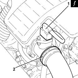
1. Disconnect the electrical connection from the air flow meter.
| Name | Connector | |
|---|---|---|
| 1 | Air flow meter | K41 |
2. Loosen the band and disconnect the the turbocharger air inlet sleeve from the rigid pipe, air flow meter side.
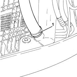
1. Loosen the band and disconnect the lower radiator coolant outlet hose from the radiator, radiator side.
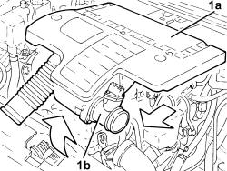
1. Remove the air filter (1a) complete with air flow meter (1b) by releasing from the underlying pins and then from the rear fastenings.
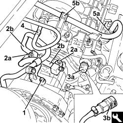
1. Undo the bolt securing the coolant pipe mounting bracket to the air conditioner compressor.
2. Undo the bolt (2a) and disconnect the coolant fluid inlet and outlet pipes (2b) from the air conditioning compressor and move aside.
3. Undo the protective plug (3a) for the fuel manifold and use tool (3b) to drain the pressure from the fuel system.
Recover the fuel which comes out in a suitable container.
| Name | Country | |
|---|---|---|
| 3b | Rapid connector | 1.870.684.000 |
4. Disconnect the rapid connector for the fuel vapour recirculation pipe from the air chamber.
5. Disconnect the rapid attachment for the fuel supply pipe (5a) from the fuel manifold and release from collar (5b).
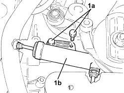
1. Undo the bolts (1a) and move the clutch operating cylinder (1b) aside without disconnecting the pipe.
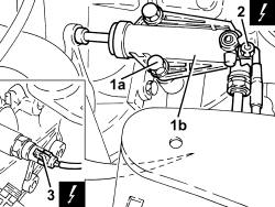
1. Undo the bolts (1a) and move the clutch operating cylinder (1b) aside without disconnecting the pipe.
2. Undo the nut and disconnect the battery earth lead from the gearbox.
| Name | Connector | |
|---|---|---|
| 2 | Battery earth | C1 |
3. Disconnect the electrical connection from the reversing lights switch.
| Name | Connector | |
|---|---|---|
| 3 | Reversing lights switch | I20 |
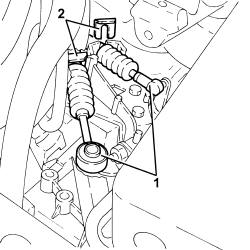
1. Disconnect the gear engagement/selector cables.
2. Remove the stops and release the gear engagement/selector cables from the mounting bracket.
1. Disconnect the brake servo single-acting valve from the brake servo.
2. Release the vacuum pipe for the brake servo (2a) from the retaining band (2b).
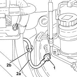
Drain the air conditioner coolant circuit - 0010T84 coolant for air conditioning system dehydrate and recharge.
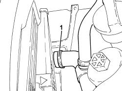
1. Loosen the band and disconnect the lower radiator coolant outlet hose from the radiator, radiator side.
Collect the engine coolant in a suitable container.
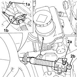
1. Undo the bolts (1a) fixing the gear selector and engagement cables mounting bracket (1b).
2. Press the release button (2a) and disconnect the gear selector cable (2b).
3. Disconnect the gear engagement cable.
Move the gear selector and engagement cables, complete with mounting bracket, sideways.
1. Loosen the band and disconnect the upper coolant inlet hose to the radiator, thermostat side.
2. Loosen the band and disconnect the heater supply and return pipe, water pump rigid inlet pipe side.
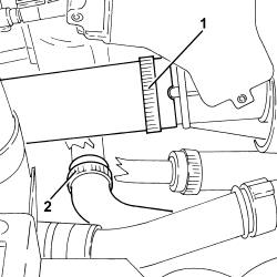
1. Loosen the band and disconnect the coolant return pipe to the climate control heater, thermostat side.
2. Loosen the band and disconnect the coolant return pipe from the climate control heater, water pump rigid inlet pipe side.
3. Release the coolatn return pipe from the climate control system heater from its bands.
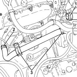
1. Loosen the band and disconnect the single heater water supply and return pipe, E.G.R. exhaust gas/water heat exchanger side.
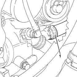
Proceed with removal - 1072C44 exhaust manifold heat shield on bulkhead - r+r
Proceed with removal - 1072C16 exhaust manifold with catalytic converter - r r
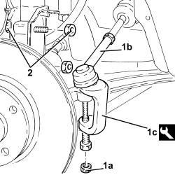
1. Undo the nuts (1a) and disconnect the track rods (1b) from the steering knuckles usiing the tool (1c).
| Name | Country | |
|---|---|---|
| 1c | Extractor | 1.871.000.700 |
2. Undo the bolts fixing the front hub steering knuckle to the front shock absorbers.
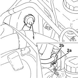
1. Disconnect the brake servo single-acting valve from the brake servo.
2. Undo the nut (2a) and disconnect the pipe from expansion valve to the compressor (2b), expansion valve side.
Seal the disconnected connectors, using suitable plugs, to prevent humidity and impurities from entering the system.
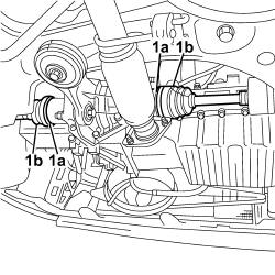
1. Loosen the bands (1a) and disconnect the driveshafts (1b ).
Secure the drive shafts.
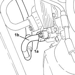
1. Undo the bolt (1a) and disconnect the pipe from the compressor to the condenser for the air conditioner (1b), compressor side.
Seal the disconnected connectors, using suitable plugs, to prevent humidity and impurities from entering the system.
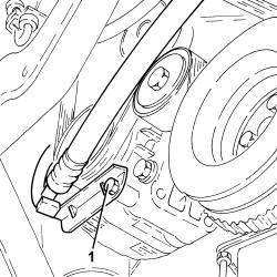
1. Undo the bolt fixing the air conditioning pipe mounting bracket to the alternator.
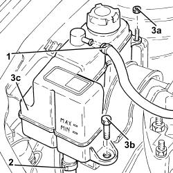
1. Loosen the band and disconnect the coolant return pipe from the engine coolant reservoir.
2. Loosen the band and disconnect the supply pipe, reservoir side, from the engine coolant reservoir.
3. Undo nut (3a), bolt (3b) and remove engine coolant reservoir (3c).
Position a hydraulic jack under the gearbox.
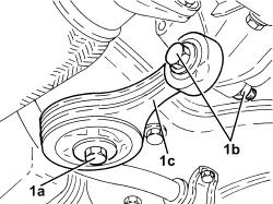
1. Undo the bolt (1a) and the bolt (1b) and remove the power unit lower reaction rod (1c).
Remove the hydraulic jack from under the gearbox.
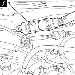
1. Disconnect the electrical connections from the diesel electronic injection control unit.
| Name | Connector | |
|---|---|---|
| 1 | Engine management control unit | M10 |
Lower the lift and place a suitable stand beneath the power unit.
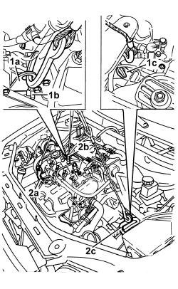
1. Position a suitable bracket (1a) by the stud (1b) under the air conditioning compressor and a special bracket (1c) on the bellhousing.
2. Secure the engine at points (2a), (2b) and (2c) near the seals positioned previously using a hydraulic lift fitted with special chains and hooks.
Lift the power unit slightly so that all cables are under the same strain.
Undo the fuel filler cap and remove it to discharge the pressure in the system.
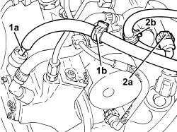
1. Disconnect the rapid connector (1a) for the fuel supply pipe from the fuel filter to the pressure pump, pressure pump side and release it from the fastening (1b).
2. Disconnect the rapid attachment (2a) for the fuel return pipe to the tank, single fuel manifold pipe side and release it from the fastening (2b).
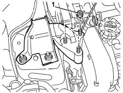
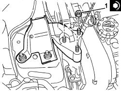
1. Undo the nuts fixing the timing side power unit support flexible mounting to the support.
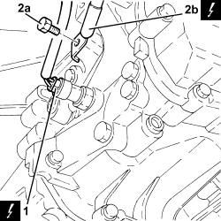
1. Disconnect the electrical connection from the reversing lights switch.
| Name | Connector | |
|---|---|---|
| 1 | Reversing lights switch | I20 |
2. Undo the bolt (2a) and disconnect the battery earth lead (2b) from the gearbox.
| Name | Connector | |
|---|---|---|
| 2b | Battery earth | C1 |
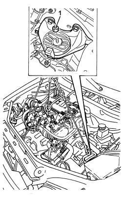
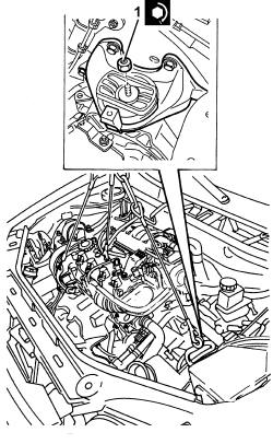
1. Undo the nut fixing the power unit gearbox side rigid support to the flexible mounting.
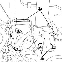
1. Undo the bolts fixing the left driveshaft to the differential internal driveshaft.
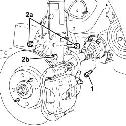
2. Undo the top bolt (2a) and loosen the bottom bolt (2b) securing the front left damper to the steering knuckle.
Move the left drive shaft away from the differential internal drive shaft and secure it as appropriate.
Slowly lower the power unit with the hydraulic hoist until it is resting on the support positioned previously.
1. Unscrew the bolts securing the right drive shaft to the intermediate drive shaft.
Recover the safety plates.
2. Undo the top bolt (2a) and loosen the bottom boltt (2b) securing the front right damper to the steering knuckle.
Move the right drive shaft away from the intermediate drive shaft and secure it as appropriate.
Refitting
Place the power unit back in the engine compartment using the hydraulic hoist.
1. Undo the nut fixing the gearbox side rigid power unit support to the flexbile mounting to the specified torque.
| Fastening | Component | Ø | Value (daNm) | |
|---|---|---|---|---|
| 1 | Bolt | POWER UNIT GEAR BOX END RIGID MOUNT | M12 | (Flexible mounting side) 8.1 ÷ 9.9 |
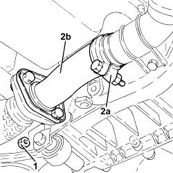
1. Tighten the nuts fastening the rigid section of the exhaust pipe between the catalytic converter and the silencer, silencer side.
Release the rigid pipe for the exhaust pipe between the catalytic converter and silencer from the silencer.
2. Loosen the collar (2a) and remove the rigid pipe for the exhaust pipe between the catalytic converter and the silencer (2b).
1. Tighten the nuts fixing the timing side power unit support flexible mounting to the support to the recommended torque.
| Fastening | Component | Ø | Value (daNm) | |
|---|---|---|---|---|
| 1 | Nut | FRONT RUBBER MOUNTS | M10 | (Rigid support side) 4.5 ÷ 5.5 |
1. Undo the bolt fixing the power unit lower reaction rod to the front suspension crossmember.
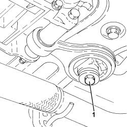
Remove the hydraulic hoist fitted with suitable chains and the brackets used for supporting the power unit.
Position a hydraulic jack under the gearbox.
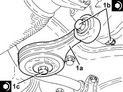
1. Place the power unit reaction rod (1a) back in its housing, then fasten by tightening bolts (1b) and (1c) to the recommended torque.
| Fastening | Component | Ø | Value (daNm) | |
|---|---|---|---|---|
| 1b | Bolt | LOWER ROD ON ENGINE | M12 | (Gearbox side) 7.2 ÷ 8.8 |
| Fastening | Component | Ø | Value (daNm) | |
|---|---|---|---|---|
| 1c | Bolt | LOWER ROD ON ENGINE | M12 | (Front suspension crossmember side) 11.4 ÷ 12.6 |
Remove the hydraulic jack from under the gearbox.
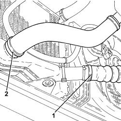
1. Loosen the band and disconnect the air supply hose between the turbocharger and the heat exchanger, heat exchanger side.
2. Loosen the band and disconnect the air supply hose from the heat exchanger to the rigid pipe, heat exchanger side.
Tighten the bolt fixing the air conditioning pipe mounting bracket to the alternator.
Connect the driveshafts and tighten the bands.
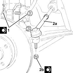
1. Tighten the front wheel hub fastening bolts to the front shock absorbers to the recommended torque.
| Fastening | Component | Ø | Value (daNm) | |
|---|---|---|---|---|
| 1 | Bolt | FRONT HUB STEERING KNUCKLE. | M10 | (Shock absorber side) 6.2 ÷ 6.8 |
2. Connect the steering rods (2a) to the front steering knuckles and tighten the nut (2b) to the recommended torque.
| Fastening | Component | Ø | Value (daNm) | |
|---|---|---|---|---|
| 2b | Bolt | EXHAUST PIPE MOUNTS/FASTENERS | M10 x 1.25 | (centre) 5 |
Proceed with removal - 7055A43 central front grille - r r
1. Disconnect the electrical connection from the engine fan motor.
| Name | Connector | |
|---|---|---|
| 1 | Engine electric fan motor | N11 |
2. Disconnect the electrical connections from the engine cooling fan resistor.
| Name | Connector | |
|---|---|---|
| 2 | Engine fan adjustment resistor | O10 |
Release the electrical wiring from the fastenings on the fan and move it aside.
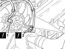
Proceed with refitting - 1072C16 exhaust manifold with catalytic converter - r r.
Proceed with refitting - 1072C44 exhaust manifold heat shield on bulkhead - r+r.
Connect the coolant return hose from the climate control heater on the side of the rigid inlet pipe to the water pump and do up the band.
Connect the engine coolant return pipe from the climate control system heater, thermostat side, and tighten the band.
Place the gear selector and engagement cables, complete with mounting bracket, back in their housings.
Connect the gear selector cable.
Connect the gear engagement cable.
Tighten the bolts fixing the gear selector and engagement mounting bracket.
Secure the vacuum pipe for the brake servo using the band.
Connect the brake servo one-way valve to the brake servo.
Connect the electrical connection to the reversing lights switch.
Connect the battery earth lead and tighten the nut.
Replace the clutch operating cylinder, then fix it tightening the bolts to the recommended torque.
| Fastening | Component | Ø | Value (daNm) | |
|---|---|---|---|---|
| Bolt | CLUTCH SLAVE CYLINDER | M8 | (Gearbox side) 1.8 - 2.2 |
Connect the rapid attachment for the fuel supply pipe to the fuel manifold pipe and secure with the band.
Connect the rapid connector for the fuel vapour recirculation pipe to the air chamber.
Connect the coolant inlet and outlet pipes to the air conditioning compressor and secure by tightening the bolts to the specified torque.
| Fastening | Component | Ø | Value (daNm) | |
|---|---|---|---|---|
| Bolt | PIPES FROM COMPRESSOR TO CONDENSOR | M6 | 0.7 ÷ 1.1 |
| Fastening | Component | Ø | Value (daNm) | |
|---|---|---|---|---|
| Bolt | EXPANSION VALVE - COMPRESSOR PIPE | M6 | 0.7 ÷ 1.1 |
Tighten the bolt securing the coolant pipe mounting brackets to the air conditioner compressor.
Connect the lower coolant outlet hose from the radiator, radiator side, and tighten the band.
Connect the upper coolant inlet hose to the radiator, thermostat side, and tighten the band.
Place the hose from the air filter to the intake manifold back in its housing, connect it to the intake manifold and tighten the band.
Connect the engine oil vapour inlet pipe to the intake manifold.
Connect the engine oil vapour intake pipe to the tappet cover and tighten the band.
Proceed with refitting - 1048A10 air cleaner filtering element - replace.
Proceed with refitting - 5530B52 Battery DRIP TRAY/SUPPORT - R.R..
Proceed with refitting - 5530B10 battery - r+r.
Proceed with refitting - 7055B91 Right front WHEEL ARCH LINER - R.R..
Proceed with refitting - 7055B66 Engine compartment DUST SHIELD protection in right front wheel arch - R.R..
Proceed with refitting - 4450B12 front or rear wheels (two) - r+r.
Refill the engine cooling system with coolant - 0010T20 coolant change.
Fill the air conditioner coolant circuit - 0010T84 coolant for air conditioning system dehydrate and recharge.
Remove the car from the ramps.
1. Undo the nut securing the upper cooling fan bracket to the upper beam.
2. Undo the side bolts fixing the radiator cooling fan to the radiator.
3. Remove radiator cooling fan (3a) after releasing lower pins (3b) from the lower radiator beam and tabs (3c) press-fitted to the radiator.
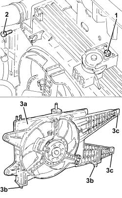
1. Support the power unit using a hydraulic hoist fitted with suitable chains connected to the special brackets on the engine.
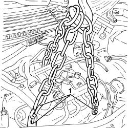
Position a suitable support under the power unit.
1. Undo the nut fixing the air conditioning system pipes mounting bracket.
2. Undo the nuts (2a) and (2b), then remove the timing side power unit support flexible mounting (2c).
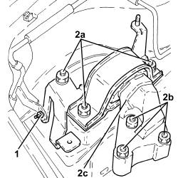
1. Undo the nut fixing the gearbox side power unit rigid support to the flexible mounting.
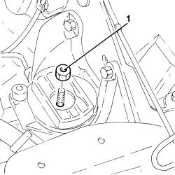
Slowly lower the power unit with the hydraulic hoist until it is resting on the support positioned previously.
Refitting
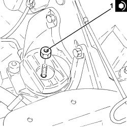
Place the power unit back in the engine compartment using the hydraulic hoist.
1. Tighten the nut securing the gearbox side rigid power unit support to the flexible mounting to the recommended torque.
| Fastening | Component | Ø | Value (daNm) | |
|---|---|---|---|---|
| 1 | Nut | POWER UNIT GEAR BOX END RIGID MOUNT | M12 | (Flexible mounting side) 8.1 ÷ 9.9 |
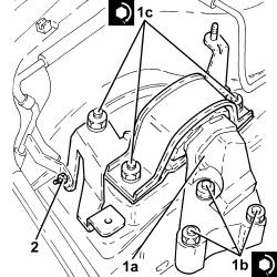
1. Place the timing side power unit support flexible mounting (1a) in position and secure it tightening the nuts (1b) and (1c) to the recommended torque.
| Fastening | Component | Ø | Value (daNm) | |
|---|---|---|---|---|
| 1b | Nut | FRONT RUBBER MOUNTS | M10 | (Rigid support side) 4.5 ÷ 5.5 |
| Fastening | Component | Ø | Value (daNm) | |
|---|---|---|---|---|
| 1c | Nut | FRONT RUBBER MOUNTS | M10 | (Bodyshell side) 4.1 ÷ 5.0 |
2. Tighten the nut securing the air conditioning system pipe bracket to the power unt flexible mounting block, timing side.
Remove the support positioned under the power unit.
Remove the hydraulic hoist fitted with suitable chains used for supporting the power unit.
Refit radiator cooling fan, securing the lower pins to the lower radiator beam and press-fitting the tabs to the radiator.
Tighten the side bolts securing the radiator cooling fan to to the radiator.
Tighten the nut securing the upper radiator cooling fan to the upper beam.
Refit the electrical wiring in its seating and attach it to the fan.
Connect the electrical connections to the resistor for the engine cooling fan.
Connect the electrical connection to the engine fan motor.
Proceed with removal - 7055A43 central front grille - r r.
Connect the air supply hose from the heat exchanger to the rigid pipe, heat exchanger side and tighten the band.
Connect the air supply hose between the turbocharger and the intercooler, heat exchanger side and tighten the band.
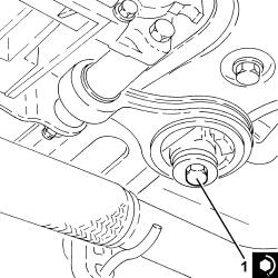
1. Tighten the bolt fixing the power unit lower reaction rod to the front suspension crossmember to the recommended torque.
| Fastening | Component | Ø | Value (daNm) | |
|---|---|---|---|---|
| 1 | Bolt | LOWER ROD ON ENGINE | M12 | (Front suspension crossmember side) 11.4 ÷ 12.6 |
Refit the rigid exhaust pipe section between the catalytic converter and the silencer and secure it using the collar.
Tighten the nuts fastening the rigid section of the exhaust pipe between the catalytic converter and the silencer, silencer side.
Connect the right drive shaft to the intermediate drive shaft.
1. Tighten the bolts securing the front right damper to the steering knuckle to the specified torque.
| Fastening | Component | Ø | Value (daNm) | |
|---|---|---|---|---|
| 1 | Bolt | FRONT DAMPER | M10 | (Front steering knuckle side) 6.2 ÷ 6.8 |
2. Tighten the bolts securing the right drive shaft to the intermediate drive shaft to the specified torque.
| Fastening | Component | Ø | Value (daNm) | |
|---|---|---|---|---|
| 2 | Bolt | FRONT DRIVE SHAFT COMPLETE WITH JOINTS | M8 | (Intermediate driveshaft side) 3.6 ÷ 4.4 |
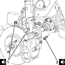
Connect the left drive shaft to the differential inner drive shaft.
1. Tighten the bolts securing the front left shock absorber to the steering knuckle to the specified torque.
| Fastening | Component | Ø | Value (daNm) | |
|---|---|---|---|---|
| 1 | Bolt | FRONT DAMPER | M10 | (Front steering knuckle side) 6.2 ÷ 6.8 |
2. Tighten the bolts fixing the left driveshaft to the left differential internal driveshaft to the recommended torque.
| Fastening | Component | Ø | Value (daNm) | |
|---|---|---|---|---|
| 2 | Bolt | FRONT DRIVE SHAFT COMPLETE WITH JOINTS | M8 | (Differential internal driveshaft side) 3.6 ÷ 4.4 |
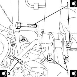
Connect the battery earth lead to the gearbox and fix it using the bolt.
Connect the electrical connection to the reversing lights switch.
Connect the rapid connector for the intermediate coupling for the tank fuel return pipe.
Connect the rapid attachment for the fuel return pipe to the tank, fuel single fuel manifold pipe side and fasten it.
Connect the rapid connector for the fuel supply pipe from the filter to the pressure pump, pressure pump side and fasten it.
Connect the electrical connections to the diesel electronic injection control unit.
Refit the coolant reservoir in its seating and secure with the nut and bolt.
Connect the engine coolant reservoir supply pipe and tighten the band.
Connect the coolant return pipe to the engine coolant reservoir and tighten the band.
1. Connect the pipes from the air conditioning compressor to the condenser (1a), compressor side and secure them tightening the bolt (1b) to the recommended torque.
Replace the O-rings for the connectors using green coloured seals only, resistant to R134a refrigerant fluid.
Lubricate the thread of the connectors using anti-freeze.
| Fastening | Component | Ø | Value (daNm) | |
|---|---|---|---|---|
| 1b | Bolt | PIPES FROM COMPRESSOR TO CONDENSOR | M6 | (Compressor side) 0.7 ÷ 1.1 |
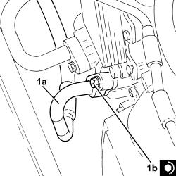
1. Connect the pipe from the expansion valve to the compressor (1a), expansion valve side and fix it tightening the nut (1b) to the recommended torque.
Replace the O-rings for the connectors using green coloured seals only, resistant to R134a refrigerant fluid.
Lubricate the thread of the connectors using anti-freeze.
| Fastening | Component | Ø | Value (daNm) | |
|---|---|---|---|---|
| 1b | Nut | EXPANSION VALVE - COMPRESSOR PIPE | M6 | (Expansion valve side) 0.7 ÷ 1.1 |
2. Connect the brake servo one-way valve to the brake servo.
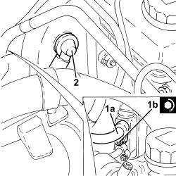
Connect the heater single coolant supply and return pipe, E.G.R. exhaust gas/water heat exchanger side and tighten the band.
Connect the heater single coolant supply and return pipe, water pump rigid inlet pipe side and tighten the band.
Connect the upper coolant inlet hose to the radiator, thermostat side, and tighten the band.
Connect the lower coolant outlet hose from the radiator, radiator side, and tighten the band.
Secure the gear engagement/selector cables to the mounting bracket with the stops.
Connect the gear engagement/selector cables.
Replace the clutch operating cylinder, then fix it using the bolts.
Replace the air filter, complete with air flow meter, in its housing.
Connect the air intake sleeve to the turbocharger, air flow meter side, and tighten the band.
Connect the electrical connection to the air flow meter.
Proceed with refitting - 5530B52 Battery DRIP TRAY/SUPPORT - R.R..
Proceed with refitting - 5530B10 battery - r+r.
Refill the engine cooling system with coolant - 0010T20 coolant change.
Fill the air conditioner coolant circuit - 0010T84 coolant for air conditioning system dehydrate and recharge.
Proceed with refitting - 7055B91 Right front WHEEL ARCH LINER - R.R..
Proceed with refitting - 7055B90 Left front WHEEL ARCH LINER - R.R..
Proceed with refitting - 7055B66 Engine compartment DUST SHIELD protection in right front wheel arch - R.R..
Proceed with refitting.
Proceed with refitting - 4450B12 front or rear wheels (two) - r+r.
Remove the car from the ramps.
Parts & tools for this job For 2003 Fiat Idea
- PARTClutch kitSearch: Fiat Idea 2003 clutch kit
- TOOLClutch alignment toolSearch: clutch alignment tool
- FLUIDGear oilSearch: Fiat Idea manual gearbox oil
Links open Amazon search results in a new tab. As an Amazon Associate I earn from qualifying purchases.