
Gear box left rigid mount - r r
- Make
- Fiat
- Model
- Idea Factory Service Manual
- Year
- 2003–2012
- Section
- Power unit supports › Gear box left rigid mount - r r
Gear box left rigid mount - r r
Removing
Position the vehicle on the ramp
Proceed with removal - 1048A10 air cleaner filtering element - replace
Proceed with removal - 1048A32 sleeve from air cleaner to intake manifold - r + r
Proceed with removal - 5530B10 battery - r+r
Proceed with removal - 5530B52 Battery DRIP TRAY/SUPPORT - R.R.
Proceed with removal - 7055A43 central front grille - r r
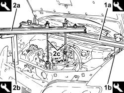
1. Fit the tool (1a), complete with support mountings (1b).
| Name | Country | |
|---|---|---|
| 1a | Crossmember | 1.870.595.000 |
| Name | Country | |
|---|---|---|
| 1b | Support mountings | 1.870.650.000 |
2. Fit the tools (2a) and (2b), then connect them using links (2c) to the brackets fitted previously.
| Name | Country | |
|---|---|---|
| 2a | Crossmember | 1.860.851.000 |
| Name | Country | |
|---|---|---|
| 2b | Vertical support | 1.871.001.300 |
Removing
Position the vehicle on the ramp
Proceed with removal - 5530B10 battery - r+r
Proceed with removal - 5530B52 Battery DRIP TRAY/SUPPORT - R.R.
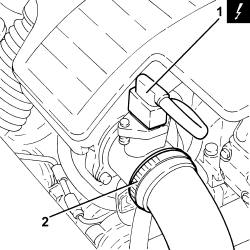
1. Disconnect the electrical connection from the air flow meter.
| Name | Connector | |
|---|---|---|
| 1 | Air flow meter | K41 |
2. Loosen the band and disconnect the the turbocharger air inlet sleeve from the rigid pipe, air flow meter side.
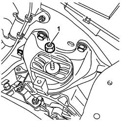
1. Undo the nut fixing the power unit gearbox side rigid support to the flexible mounting.
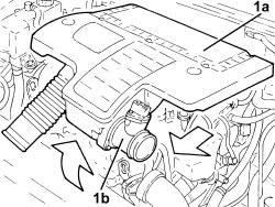
1. Remove the air filter (1a) complete with air flow meter (1b) by releasing from the underlying pins and then from the rear fastenings.
Proceed with removal - 4450B02 left front wheel r r
Proceed with removal - 7055B90 Left front WHEEL ARCH LINER - R.R.
1. Undo the bolts (1a) and remove the gearbox side rigid power unit support (1b).
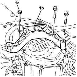
Proceed with removal - 7055A43 central front grille - r r
1. Fit a suitable bracket (1b) using the bolt (1a) shown securing the camshaft housing.
This bracket is used exclusively for balancing the power unit.
2. Fit the tool (2a), complete with support mountings (2b).
| Name | Country | |
|---|---|---|
| 2a | Crossmember | 1.870.595.000 |
| Name | Country | |
|---|---|---|
| 2b | Support mountings | 1.870.650.000 |
3. Fit the tools (3a) and (3b), then connect them via the links (3c) to the bracket previously fitted and to the exhaust manifold.
| Name | Country | |
|---|---|---|
| 3a | Crossmember | 1.860.851.000 |
| Name | Country | |
|---|---|---|
| 3a | Vertical support | 1.871.001.300 |
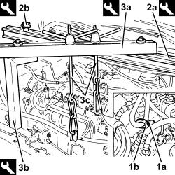
Refitting
1. Refit the gearbox side power unit rigid support (1a) in its seating and tighten the bolts (1b) to the specified torque.
| Fastening | Component | Ø | Value (daNm) | |
|---|---|---|---|---|
| 1b | Bolt | POWER UNIT GEAR BOX END RIGID MOUNT | M10 | (Gearbox side) 4.5 ÷ 5.5 |
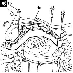
1. Undo the nut fixing the power unit gearbox side rigid support to the flexible mounting.
Proceed with removal - 7055B90 Left front WHEEL ARCH LINER - R.R..
Proceed with removal - 4450B02 left front wheel r r.
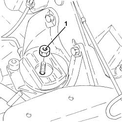
1. Undo the nut fixing the gearbox side rigid power unit support to the flexbile mounting to the specified torque.
| Fastening | Component | Ø | Value (daNm) | |
|---|---|---|---|---|
| 1 | Nut | POWER UNIT GEAR BOX END RIGID MOUNT | M12 | (Flexible mounting side) 8.1 ÷ 9.9 |
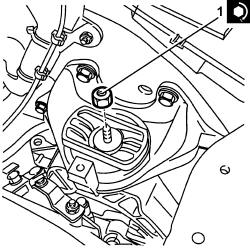
Proceed with removal - 4450B02 left front wheel r r
Proceed with removal - 7055B90 Left front WHEEL ARCH LINER - R.R.
1. Undo the bolts (1a) and remove the gearbox side rigid power unit support (1b).
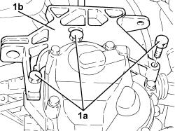
Remove the safety tools used for supporting the power unit.
| Name | Country | |
|---|---|---|
| Crossmember | 1.870.595.000 |
| Name | Country | |
|---|---|---|
| Support mountings | 1.870.650.000 |
| Name | Country | |
|---|---|---|
| Crossmember | 1.860.851.000 |
| Name | Country | |
|---|---|---|
| Vertical support | 1.871.001.300 |
Proceed with refitting - 7055A43 central front grille - r r.
Proceed with refitting - 5530B52 Battery DRIP TRAY/SUPPORT - R.R..
Proceed with refitting - 5530B10 battery - r+r.
Proceed with refitting - 1048A32 sleeve from air cleaner to intake manifold - r + r.
Proceed with refitting - 1048A10 air cleaner filtering element - replace.
Remove the car from the ramps.
Refitting
1. Refit the gearbox side power unit rigid support (1a) in its seating and tighten the bolts (1b) to the specified torque.
| Fastening | Component | Ø | Value (daNm) | |
|---|---|---|---|---|
| 1b | Bolt | POWER UNIT GEAR BOX END RIGID MOUNT | M10 | (Gearbox side) 4.5 ÷ 5.5 |
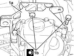
Proceed with refitting - 7055B90 Left front WHEEL ARCH LINER - R.R..
Proceed with refitting - 4450B02 left front wheel r r.
1. Undo the nut fixing the gearbox side rigid power unit support to the flexbile mounting to the specified torque.
| Fastening | Component | Ø | Value (daNm) | |
|---|---|---|---|---|
| 1 | Nut | POWER UNIT GEAR BOX END RIGID MOUNT | M12 | (Flexible mounting side) 8.1 ÷ 9.9 |
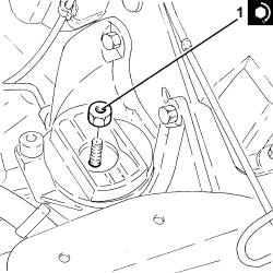
Remove the safety tools used for supporting the power unit.
| Name | Country | |
|---|---|---|
| Crossmember | 1.870.595.000 |
| Name | Country | |
|---|---|---|
| Support mountings | 1.870.650.000 |
| Name | Country | |
|---|---|---|
| Crossmember | 1.860.851.000 |
| Name | Country | |
|---|---|---|
| Vertical support | 1.871.001.300 |
Remove the bracket and tighten the bolt fixing the camshaft housing to the recommended torque.
| Fastening | Component | Ø | Value (daNm) | |
|---|---|---|---|---|
| Bolt | CYLINDER HEAD EXTENSION | M7 | (Lower cylinder head side) 1.8 |
Proceed with refitting - 7055A43 central front grille - r r.
Replace the air filter, complete with air flow meter, in its housing.
Connect the air intake sleeve to the turbocharger, air flow meter side, and tighten the band.
Connect the electrical connection to the air flow meter.
Proceed with refitting - 5530B52 Battery DRIP TRAY/SUPPORT - R.R..
Proceed with refitting - 5530B10 battery - r+r.
Remove the car from the ramps.
Parts & tools for this job For 2003 Fiat Idea
- PARTEngine gasket setSearch: Fiat Idea 2003 engine gasket set
- TOOLTorque wrenchSearch: 3/8 inch torque wrench
- TOOLFeeler gauge setSearch: feeler gauge set
Links open Amazon search results in a new tab. As an Amazon Associate I earn from qualifying purchases.