
Rpm and TDC sensor
- Make
- Fiat
- Model
- Punto (176) Factory Service Manual
- Year
- 1993–1999
- Section
- Fuel system (1372 T) › Rpm and TDC sensor
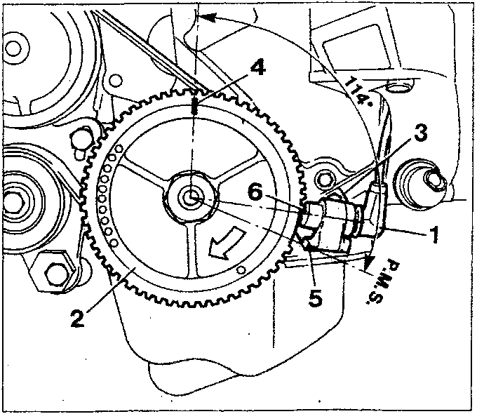
- Sensor
- Phonic wheel
- Sensor mount
- TDC reference notch on phonic wheel
- TDC reference notch on sensor mount
- Synchronism tooth
RPM AND TDC SENSOR
The phonic wheel consists of 58 teeth plus a space equivalent to the bulk occupied by two suppressed teeth.
The reference defined by the space of the two missing teeth is used as a basis for measuring the synchronism point (TDC).
The synchronism point is delimited by tooth (6). When this passes beneath the sensor, the crankshaft is located with piston pair 1-4 at 114° before TDC.
This signal is used by the ECU to compute the ignition advance angles.
INJECTION TIMING SENSOR
The Bosch Motronic M2.7 system is sequential and phased, i.e. fuel injection takes place in sequence for each cylinder during the intake phase.
To achieve this, the ECU uses a signal that determines the injection point on the basis of a signal from the rpm and TDC sensor.
The signal sent to the ECU is produced by a sensor fitted to the auxiliary shaft.
The sensor consists of a Hall effect transducer, a rotor and a cover.
Hall's principle;
"A semiconducting crystal with current flowing through it, within a normal magnetic field (force lines at right angles ot current direction) generates a potential difference at its terminals, known as the Hall voltage."
The rotor consists of a sheet steel ring with a slot (missing part). The rotor ring moves to cover the transducer and set up a high signal (5V); when the Hall transducer is free (missing part) a low signal is generated (0V)
Low and high signals therefore alternate once every two crankshaft turns and specifically when cylinder no. 4 is in compression phase 108° before TDC.
This signal, together with the rpm and TDC signal, allows the ECU to recognise the cylinders and determine the point of injection.
NOTE See following pages for exact sensor positioning (timing adjustment)
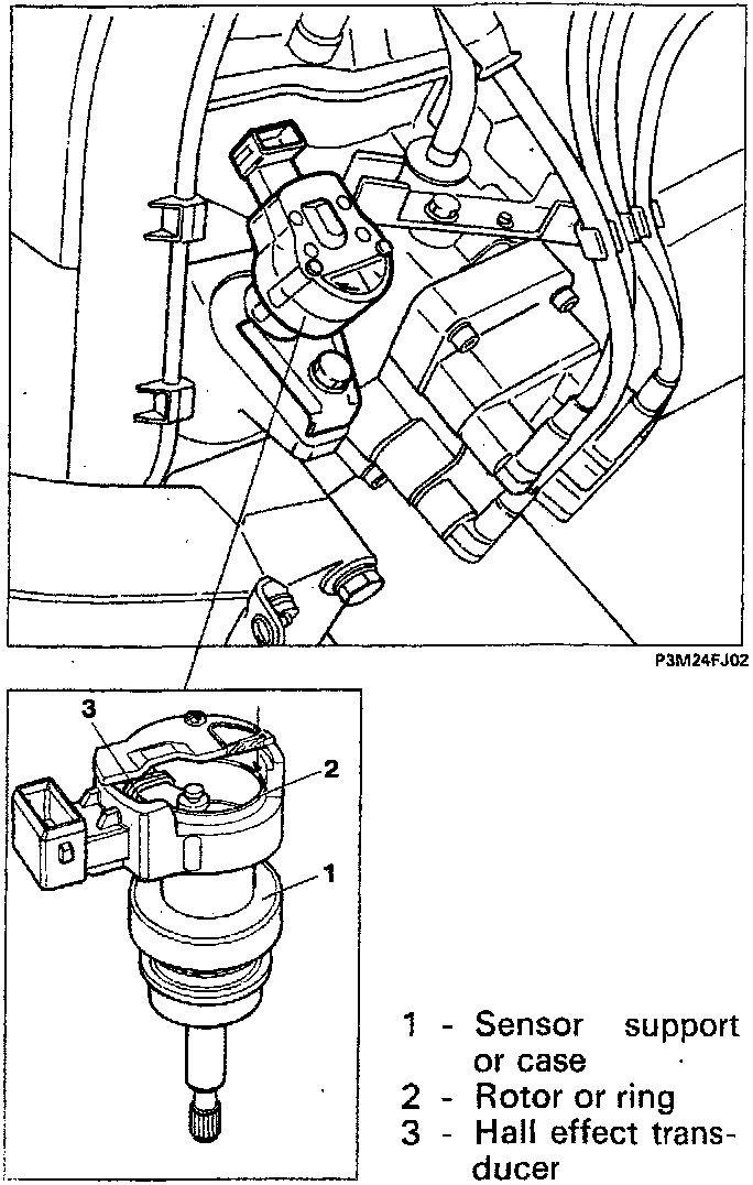
- Sensor support or case
- Rotor or ring
- Hall effect transducer
Parts & tools for this job For 1993 Fiat Punto
- TOOLOBD2 scannerSearch: OBD2 scanner
- TOOLDigital multimeterSearch: automotive digital multimeter
- TOOLBack-probe test leadsSearch: back probe test leads
Links open Amazon search results in a new tab. As an Amazon Associate I earn from qualifying purchases.