
Cleaner 134
- Make
- Fiat
- Model
- Punto (176) Factory Service Manual
- Year
- 1993–1999
- Section
- Heating/ventilation › Cleaner 134
CLEANER 134
MAIN COMPONENTS
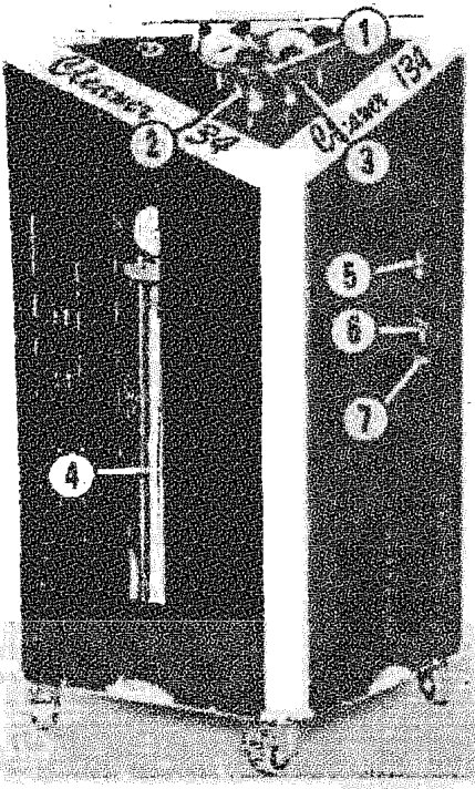
The Cleaner 34 (figure alongside) consists of a console with two triangular plastic panels at the top: one flat tray that acts as a collector and one tilted panel along which are arranged various electrical components in a line at the top (on the horizontal diagonal). At the front, toward the front corner in horizontal position, is a pressure gauge assembly (1).
Four diagrams are attached to the outer surface of the metal moulding that divides the two surfaces above. These describe the operations to be carried out as part of the different functions.
Two hoses (blue and red) for connection to the vehicle heating/ventilation system can be connected to the pressure gauge assembly via two fittings (2 and 3).
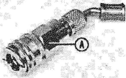
A quick-release fitting (A) is fitted to the free end of each hose
An opening that provides access to dispensing cylinder (4) is located in the panel that forms the left top outer cover to the device.
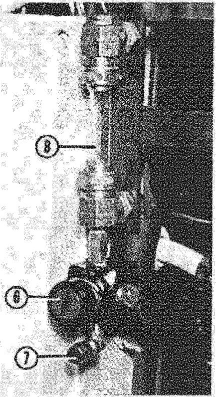
Two openings located vertically one above the other are arranged in the middle part of the panel that forms the right front outer cover to the device; the top opening (5) provides a view of the quantity of oil (separated from coolant) that has built up in column (B). This may be drained through fitting (7) by opening the cock (6) that emerges from the second opening (lower).
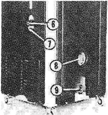
Two openings are located in the lower middle part of the panel that forms the right lower outer cover of the device. The knob of the master switch can be turned through the round upper opening (8), while the lower opening (concealed by a cover) provides access to the supply lead socket (9).
The parts listed and described on the following pages are housed inside the device case and connected by electrical wires or hoses.
Parts & tools for this job For 1993 Fiat Punto
- TOOLA/C manifold gauge setSearch: AC manifold gauge set
- TOOLUV leak detection kitSearch: AC UV leak detection kit
- PARTCabin filterSearch: Fiat Punto 1993 cabin filter
Links open Amazon search results in a new tab. As an Amazon Associate I earn from qualifying purchases.